Test Instruments Part 5
|
|
Here is Part 4. Test Instruments Part 5 - The Vacuum-Tube Voltmeter - A.C. and Ohmmeter Ranges  By Larry Klein, By Larry Klein,
Technical Editor
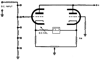
Fig. 5 - A simplified d.c. voltage measuring circuit showing the range switch and bridge circuit.
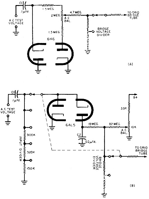
Fig. 6 - Two typical voltage-doubling rectifiers used in VTVMs. The diodes' contact potentials buck each other in (A) and the "A.C. Bal" pot selects the zero point. In (B) the negative potential is bucked against B-plus voltage tapped off the "A.C. Bal" pot.
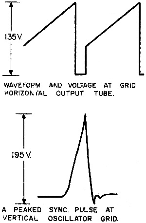
Fig. 7 - Typical waveforms from a standard television set.
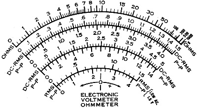
Fig. 8 - Note relationship between r.m.s. and P-P scales. P-P scale is 2.83 times larger than r.m.s. scale.
Fig. 9 - Circuit diagram of an ohmmeter section of a vacuum-tube voltmeter.
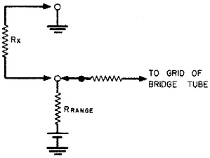
Fig. 10 - Simplified input and range circuits of VTVM ohmmeter section. The unknown d.c. voltage connected to the input terminals is applied across the entire range switch voltage divider. Maximum on-scale reading is obtained by setting the range switch at the proper voltage divider tap. The unknown d.c. voltage is now applied to the input grid of the bridge - unbalance of the triodes results and the meter deflects. So much for the d.c. bridge. A.C. Voltage Measurement. What do we have to do to enable the d.c. bridge to respond to a.c.? Why not simply rectify the unknown a.c. voltage and then apply the resultant d.c. to the bridge input as we would any d.c. voltage? That's actually what the standard VTVM does. Unfortunately, however, a number of electronic bugs appear which prevent a simple diode circuit from being used, and the circuits in actual practice usually look like those in Fig. 6. Why the complications? Let's take a close look at Fig. 6 (A). On one half of the cycle, the a.c. voltage to be measured is fed through capacitor C1 to the cathode of one diode of the 6H6 tube, and thence to ground, The capacitor, of course, gets charged in the process. On the positive-going part of the a.c. cycle, no current flows through the first diode, C1 discharges and adds its voltage to that developed across the three resistors connected to the plate of the second, conducting diode. If we look carefully at the circuit, we'll recognize a type of voltage doubler. Why a voltage doubler? Well, remember we need to get a d.c. voltage out of the rectifier circuit which is at least as high as the a.c. input voltage. Taking into account the voltage drop across the various components in the circuit, obviously some technique is needed to soup up the d.c. output ... and that's what the doubler does. Further circuit complications arise from a phenomenon called contact potential. It seems that vacuum tubes, including diodes, tend to develop a small potential between the elements. If allowed to remain, this slight voltage in the 6H6 would cause a spurious reading on the low a.c. ranges. However, placing the a.c. balance control between the two oppositely connected diodes, exact compensation can be made by bucking out the opposing contact voltages. Since the center contact of the a.c. balance potentiometer is also the take-off point for the d.c. output, about half the d.c. developed across the three resistors is lost by tapping off at this point. Actually, this is of small consequence, because the d.c. voltage across the three resistors is equal to more than the peak of the r.m s. a.c. input voltage, so we have volts enough to spare to provide an r.m.s. reading. R.M.S. and P-P. The key words in that last sentence were "r.m.s, reading," which brings us to Fig. 6(B). Slightly more complicated than the rectifier discussed above, this circuit also makes use of a doubler circuit. Because of the low breakdown voltage of the 6AL5 tube, a voltage divider (in addition to the one in the grid of the bridge tube) is needed to prevent the tube from "arcing out" at the higher peak voltages. As shown, the a.c. input voltage divider is part of the range switch and is, therefore, mechanically coupled to the bridge divider. Perhaps you're wondering why the extra resistors at the a.c. input don't cause a large difference in scale calibration between the a.c. and d.c. ranges. The VTVM takes care of that by switching the last three bridge voltage divider resistors out of the grid circuit when set up for an a.c. reading. Whereas the job of the second diode in Fig. 6(A) is mainly to cancel out the contact potential of the first diode, the second diode of Fig. 6(E) has a different story to tell. Both diodes in Fig. 6(B) are used in a complete voltage-doubler hookup which charges C2 to the full peak voltage of the incoming waveform. Contact potential cancellation voltage is obtained from a tap across the VTVM's B-plus supply. The waveforms shown in Fig. 7 are taken from a standard TV set. You can imagine the difficulties an r.m.s. calibrated a.c. meter would have translating them to any sort of meaningful reading. Even putting a peak-to-peak reading scale on the meter face (it would be the r.m.s. scale x 2.83) wouldn't help much because the reading would still only be accurate for sine-wave inputs. However, the P-P a.c. rectifier finds no difficulty in smoothing down these weird-looking spikey TV waveforms into an exact d.c. equivalent and then feeding them to the bridge circuit. The exact relationship between the P-P scales on a standard peak-reading VTVM is shown in Fig. 8. Resistance Measurement. One of the first things that hits your eye in the ohmmeter section of the VTVM is the R x 1 meg. range switch position. With the last scale division on the meter face marked 1000, this means that the VTVM can read up to a 1000 x 1 million or a billion ohms! The ohmmeter section of the average VTVM resembles the one shown in Fig. 9. The string of seven resistors may differ in value somewhat depending on the exact scales used and whether they are arranged in series, as shown, or switched individually. But the principle of operation remains the same, as we shall see. Suppose we redraw the range switch and input circuit of Fig. 9 into the form of Fig. 10. We will use only one range resistor (Rrange) and connect the resistor to be measured (Rx) to the VTVM's input terminals. The bridge circuit remains the same and we will ignore it for now. The first thing to do when using a VTVM ohmmeter is to "zero" it. Short the input leads together and adjust the Zero Adj. control for a zero reading on the meter scale. Then, unshort the leads of the VTVM and the needle will immediately swing to the right-hand side of the meter face. Now adjust the meter to ∞ (infinite) ohms. Let's see what the preceding adjustments have accomplished in terms of the internal electronics of the VTVM. Zero-adjusting the meter with the leads shorted has shorted out the battery through resistor Rrange to ground and removed the voltage from the grid of the bridge tube. Unshorting the test leads restores the battery voltage to the grid and the meter swings full scale. The Ohms Adj. knob, which is in the same spot as the A.C. and D.C. Cal. controls in the other circuits, adjusts the sensitivity of the meter so that the applied battery voltage swings the meter needle exactly to the infinite ohms scale marking on the meter face. Suppose a 100-ohm resistor (Rx) is connected across the input leads and Rrange is also set at 100 ohms. The voltage present at the grid of the bridge tube will be exactly halved, and the meter will read half scale. Now if you look at the top scale of the meter face shown in Fig. 8, you'll see that the center of the scale indicates exactly 10. If Rx were a 30-ohm resistor, for example, the shunting effect across Rrange would be increased and even less voltage would reach the bridge tube. A higher value resistor as Rx and a higher meter reading results. The only trick involved, and the reason why it's so difficult for some home constructors to build their own ohmmeters, is the scale calibration. As can be seen in Fig. 8, the scale divisions are widely spaced at the right side of the meter face and narrow down towards the left. A little thought as to how parallel resistors divide current will tell you why that is so. The Function Switch. In talking about the VTVM, we've left out practically any reference to the function switch. Since these switches are so difficult to show schematically in an understandable way without a prolonged discussion of each switch position and what it accomplishes, we thought it best to save them till last. The function switch is usually specially made for each manufacturer's VTVM and, if analyzed, generally works out to be a five-pole, five-position unit. Some of its jobs include switching the input jacks to the proper circuit, connecting in the correct calibration control for each function, reversing the meter movement connections for plus and minus d.c. and, in some cases, even turning the VTVM on and off. If you're curious, a complete schematic of the RCA "VoltOhmyst" VTVM kit is shown on page 79 of this issue and should answer any questions you may have about the specific connections of the function switch. Next month we will put the VTVM "to work in an area in which it's practically indispensable - repairing a hi-fi amplifier. The basic Williamson amplifier should be a good subject, and we will learn how to troubleshoot one and what sort of measurements the VTVM will turn up in working and non-working models.
Posted December 27, 2022 |
|