U.S. Air Force's New Radar Height Finder |
|
Aside from the photos of cool radar antennas, "Made by General Electric of Syracuse, N.Y.," caught my attention because I actually spent a couple years there (it was a different company by then) in the mid 1990s as an engineer working with a design team for a weather radar for the FAA. It was a kludge of left-over components and assemblies from other cancelled programs. The phased array antenna came from a Navy shipboard program, and the components for the RF, analog, and digital portions were cobbled together mostly from parts that were in the company stock room inventory. Very little money was budgeted for new parts or personnel (5 full-time engineers and a manager, and an occasional technician if I recall correctly). I handled all the RF and analog design and the equipment rack power supplies, plus RF plumbing out of the building and into the phased array antenna (2 other engineers handled the antenna assembly). One of the coolest parts of the design was the waveguide. I wish I had pictures of the rack and waveguide assemblies, but doing so was not permitted. It was a grueling year and a half of simulation (on very slow old Unix computers), documentation, building (I did almost all of most of my own assembly and the rack cabling), testing, integration, more testing, then moving everything out to the open air test site and testing again. 60-80 hour weeks were the norm. The guys I worked with on the digital, software, and systems were incredibly brilliant; I was definitely a dim bulb in their presence, but I managed to get my part working. After moving on to another company, I later learned that a site maintenance worker disconnected the lightning protection bonding cable to the equipment building while plowing snow, forgot to re-connect it, and a lightning strike fried a large portion of the rack. I'm glad I wasn't around to have to repair that mess! U.S. Air Force's New Radar Height Finder
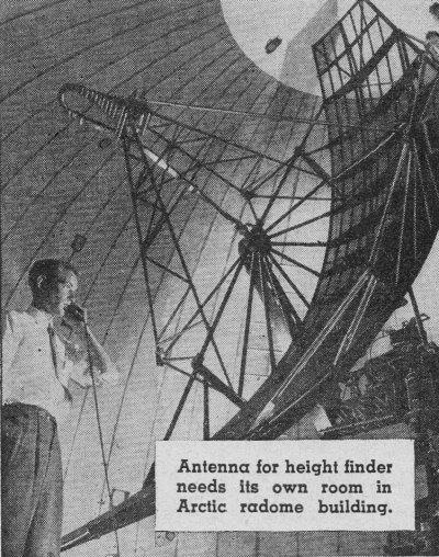
Antenna for height finder needs its own room in Arctic radome building. Defense networks of the United States and its allies are being strengthened by a powerful new radar height-finder. Made by General Electric of Syracuse, N.Y., the new radar set furnishes high-frequency energy which is concentrated in a narrow beam like that of a searchlight. This beam detects planes three times as far as previous units of this type. Its exact range is classified information. An interesting sidelight is that the energy radiated is so powerful, it can light fluorescent lamps over a hundred feet away, and can ignite flashbulbs tossed in the air in front of the antenna (see photo). The radar height-finder is being used in conjunction with search radar to detect high flying aircraft and to provide information on distance, altitude; and flight direction. The new radar is being made in mobile as well as fixed versions. A large quantity has already been supplied for use in strengthening the "radar fences" that guard the North American continent, and for defense posts in countries receiving aid from the United States under the Mutual Defense Assistance Pact. Additional units are being produced for similar use. As shown in the photos, the complete installation is a complex one, requiring the combined efforts of several trained technical personnel for successful operation. In this set-up, the height-finder and the search radars work as a team. The type of data supplied by search radar (see article in Popular Electronics, November 1954) is combined with the data available from the height-finder. The information thus obtained is fed to a central control room, where it is evaluated and interpreted. Then, in turn, it is relayed to fighter bases, from which points necessary action can be taken.
Height finder and search radars work as a team. Data is fed from radars to this control center in the radome building, and is then relayed to fighter bases.
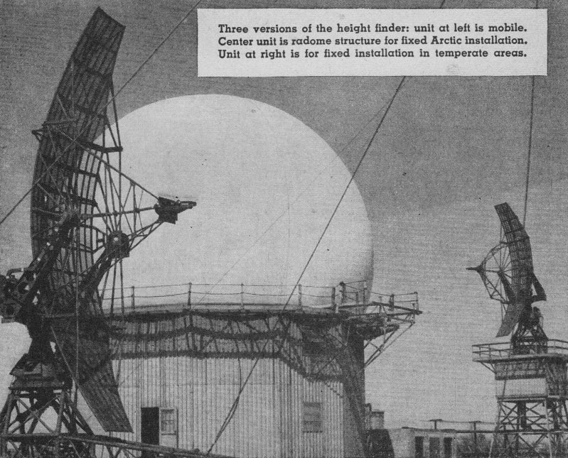
Three versions of the height finder: unit at left is mobile. Center unit is radome structure for fixed Arctic installation. Unit at right is for fixed installation in temperate areas. In Arctic climates the radar is housed in a dome-shaped circular structure (see photo) with a balloon-like radome made of woven glass fabric impregnated with a rubber compound. The radome is supported by air pressure, about a half pound per square inch, and can withstand winds up to 125 miles per hour. The radome protects the radar antenna from Arctic weather.
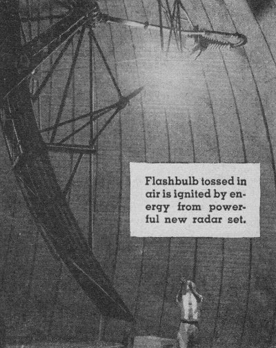
Flashbulb tossed in air is ignited by energy from powerful new radar set.
Posted November 17, 2021 |
|