The Tube Family Tree - Klystrons & Magnetrons
(Part 3)
|
|
Magnetron, photomultiplier, traveling wave, compactron, klystron, backward wave, pencil, lighthouse, cathode ray, indicator, nuvistor, acorn, peanut, T−R, electrostatic, cat's-eye, orithon, and loctal, are just a few of the many types of vacuum tubes that have been and in some cases still are in use in various types of electronic equipment. Some you have heard of, others you probably have not. All are discussed in a series of three articles published in Popular Electronics magazine. This is part 3, which includes operational descriptions of klystrons, magnetrons (in your microwave oven), and traveling wave tubes (radar & satellite communication), all of which are still designed into new products today. Here is a great webpage for magnetron operational theory that includes animations. The Tube Family Tree Part 1, Part 2 and Part 3. The Tube Family Tree - Part 3  By Louis E. Garner, Jr. Tubes amplify weak signals, but they also do many other vital electronic jobs, as this final part shows What about the future of the vacuum tube? Will designers continue to develop tubes based on new principles, and improve tubes employing already-known ones? The answer to this question is probably "yes," and a good look at the types discussed in this final portion of the tube "family tree" should convince anyone that the end is certainly not in sight. The family history of the cathode-ray tube alone ably illustrates how present-day tubes are built on past developments and discoveries. The first ancestor of the CRT was in actual operation in 1897, nine years before De Forest's triode put amplification into the hands of electronic researchers. Even so, practical television had to await development of more sophisticated CRT's, and particularly that much more unprecedented invention, the camera tube. Camera Tubes. Used in television cameras, these tubes produce a video signal corresponding to the light image of a picture or scene which is to be televised, recorded on tape, or transmitted over a wired installation. In general, camera tubes consist of an electron gun assembly, a means for deflecting the electron beam in a regular pattern. and a photosensitive target assembly of some type which can convert light patterns into electrical charges or signals when struck by the electron beam. The electron guns and deflection techniques used with camera tubes are basically like those used with display-type CRT's. The iconoscope was, for a number of years, the most practical type of camera tube. The heart of this device is a sensitized target on which the scene to be televised is focused by a lens system. The target is of sandwich-like construction and consists of a conductive coating or signal plate, a layer of insulation, usually mica, and a mosaic pattern of tiny photoemissive globules. Each globule acts somewhat like a miniature photocell. When light strikes a globule, it emits electrons to a greater or lesser extent depending on the intensity of the light. These electrons are picked up by a collector ring in front of the photo-mosaic, leaving a greater or lesser positive charge on each globule. The globules and the insulated signal plate behind them thus act as a capacitor. As the beam from the iconoscope's electron gun strikes each globule, it restores the electrons lost by photoemission, and, in effect, discharges the capacitor, developing an output signal at the signal plate. The signal corresponds to the image of the scene being televised.
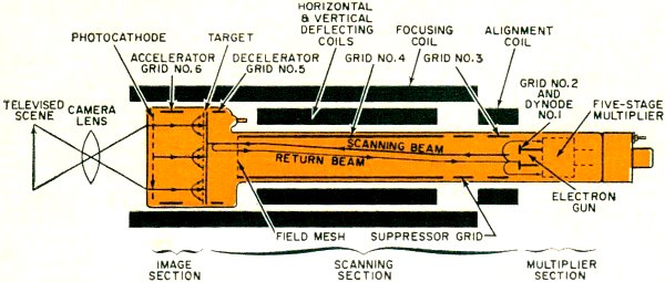
The image orthicon is one of the most complex, precise vacuum tubes in common use. The Image Orthicon. Today, the most sensitive and widely used type of camera tube is the image orthicon. It is made up of three principal parts: an image section; a scanning section; and an electron multiplier. The image section of the tube contains a semitransparent photocathode on the inside of the glass faceplate, an accelerating grid (No.6), and a target which consists of a thin glass disc with a fine mesh collector screen positioned very close to it on the photocathode (front) side. Focusing is accomplished by means of a magnetic field produced by an external coil and by the proper selection of photocathode and accelerating grid voltages. In operation, the scene to be televised is focused on the photocathode, which emits electrons proportional to the intensity of the light striking each of its areas. The electron streams are focused on the target and cause secondary electrons to be emitted by the glass disc. These secondary electrons are collected by the adjacent wire mesh, leaving the photocathode side of the disc with a pattern of positive charges corresponding exactly to the image being televised. Since the glass is quite thin, a similar charge pattern is set up on its opposite side. The glass is scanned by a low-velocity electron beam produced by an electron gun and deflected by external electromagnetic coils. This beam is made to decelerate and to approach the glass vertically at essentially zero velocity by the potentials applied to the decelerator grid (No.5) and the field mesh. Some of the electrons are deposited on the glass to neutralize its positive charge while others are repelled to form a return beam. The return electron beam, then, is modulated by the positive charge pattern on the target and hence in accordance with the original light image. On coming back to the electron gun area, the return beam passes through a five-stage electron multiplier similar to that employed in photomultiplier tubes, developing an output video signal. The dynodes in the multiplier section may amplify the modulated beam by 500 times or more, with the result that the image orthicon is basically more sensitive than the human eye in picking up faint light images. The monoscope is a special type of camera tube. Its basic principle of operation is similar to that of other CRT's, for it incorporates essentially the same type of electron gun and deflection systems. However, it is fitted with a permanently installed fixed pattern - such as a TV test pattern - and develops only a repetitive video signal. Special CRTs. In addition to the cathode-ray tubes we've discussed, there are a number of special types which depend on electron beams for their operation. Among these are a variety of discharge and demonstration tubes used for classroom study and laboratory experiments, but by far the most common type is the X-ray tube.
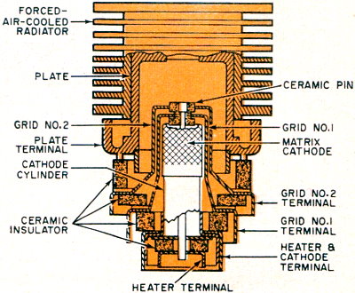
The light-house design raises the upper frequency limit for conventional negative-grid vacuum-tube amplifiers.
High transconductance, close element spacing, and very low lead inductance are the design factors responsible for the good performance of the light-house tube at frequencies up to 3000 mc. The basic X-ray tube consists of two principal electrodes: an electron source (cathode) , and a target anode. The anode is of dense metal and set at an angle with respect to the electron source. In operation, extremely high voltages are applied to the two electrodes, accelerating the electron stream to tremendous velocities. On striking the target anode, the electron beam excites the metal atoms, causing them to emit ultra-short electromagnetic radiation - X rays. Since the target is set at an angle, the X rays are radiated out through the side of the tube's glass envelope, where they can be photographed and used to trace in outline the interior make-up of solid matter. UHF Tubes. Conventional receiving and transmitting electron tubes cannot be used effectively at ultra-high and super-high radio frequencies, that is, from five hundred to tens of thousands of megacycles. At these frequencies, short lead lengths begin to have considerable inductive reactance and act like. coils or even r.f. chokes, minute inter-electrode capacities become short circuits, and even the time required for an electron to move from a cathode to a plate may represent several cycles of the frequency to be handled. When even higher frequencies are considered, familiar tuned circuits cannot be used and are replaced by resonant cavities - essentially hollow, metal-enclosed spaces which behave like tuned circuits. Tube manufacturers have designed a number of special tubes for use at extremely high frequencies. In general, these tubes have close electrode spacing to reduce electron transit time and, often, disc-shaped electrodes to reduce terminal lead inductance. Interelectrode capacities are minimized by keeping electrode supports small and shaping them for maximum spacing with respect to other tube elements. Due to their construction, many UHF tubes take on strange and unusual shapes, and are often named after their physical appearance. Thus, one firm may offer long, slim "pencil" tubes, while others produce stepped tower-like "light-house" tubes, and so on. Quite frequently, the tubes are manufactured with resonant cavities as an integral part of their structure. One pencil-type triode oscillator tube, the RCA 7533, is made with two built-in resonant cavities, one between grid and cathode and another between grid and plate. The tube looks very much like a small can. Designed for use as an oscillator in the 1660-1700 mc. band, the 7533 has a plate dissipation rating of 3.6 watts and can deliver approximately 500 milliwatts. Another interesting UHF tube is the RCA 7457, a beam power type which can be used at frequencies up to 2000 mc. With a maximum plate dissipation rating of 115 watts, it can handle input powers as high as 180 watts up to 1215 mc. Used as a class C amplifier with 900 volts on its plate, it can deliver approximately 40 watts at 1215 mc. It is designed for forced-air cooling and has a built-in finned radiator. In general, the 7457 is used with external cavities, coaxial-cylinder, or parallel line circuits. The GE GL-6299 is a co-planar triode suitable for use as an amplifier at frequencies as high as 3000 mc. Designed for use in receivers, it has an extremely low noise rating. As a rule, it is used with external cavities or coaxial circuits. Of ceramic construction, the GL-6299 generally resembles the "light-house" tube of a few years ago. The UHF tubes we've just examined, as well as many similar types, operate on the same principles as more conventional electron tubes, except for their frequency of operation and the types of tuned circuits with which they are used. In addition, however, there is a group of high-frequency tubes which operate on entirely different principles: magnetrons, klystrons, traveling-wave tubes, and related types. We'll examine these next.
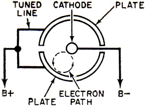
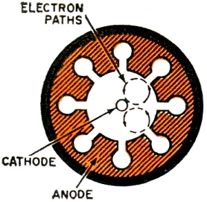
Magnetron operation depends upon interaction between the electron stream and a strong, constant magnetic field.
For efficient magnetron operation, a definite relationship between plate voltage and magnetic field strength in the interaction space must always be maintained.
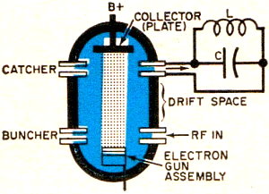
The multi-cavity magnetron has advantages that are important in practical radar applications. The Magnetron. Although used extensively since World War II as high-power oscillators in radar transmitters and other types of ultra-high frequency equipment, the magnetron is basically a diode. In its common form, it consists of a coaxial cathode and a circular anode (or plate) which may, or may not, be split into two or more segments. This assembly is placed between the poles of a powerful permanent or electromagnet and aligned so that the magnetic field is coaxial with the cathode and plate. In operation, a high positive voltage is applied to the magnetron's plate. If it were not for the magnetic field, the electrons emitted by the cathode would travel in a straight, radial line directly to the plate. The magnetic field, however, forces the electrons to travel in a spiral or circular path; and if the field is made strong enough, most of the electrons swing in complete circles, returning to the cathode. These high-speed electrons, whizzing by the plate structure, induce high-frequency currents. To obtain oscillation, then, a proper balance between anode voltage and magnetic field strength is needed, for the electron resonance must approximate that of the resonant cavity formed by the plate structure. A split-anode magnetron can be made to oscillate at frequencies much below the natural electron resonant frequency by connecting the segments to a tuned circuit, such as a tuned line. In higher frequency types, the tuned circuit may be little more than a heavy bar of metal connecting the segments together to form a simple closed loop. Split-anode magnetrons need not be limited to two segments; four, six, eight, or more segments may be used. A different type of magnetron employs a solid anode in which small resonant cavities have been formed. The high-speed electrons moving past the cavity openings shock the cavities into oscillation. The action is somewhat analogous to what happens when a person blows sharply across the open end of a small closed tube to produce a whistle. Commercially available magnetrons operate at frequencies from a few hundred to as high as 30,000 mc. and can deliver peak output powers ranging up to 2000 kw. (2 megawatts!) when used as pulse generators, or hundreds of watts when used as c.w. sources. The Klystron. In one sense a special type of cathode-ray tube, for it utilizes an electron gun and a stream of electrons for its operation, the klystron can be used as an ultra-high frequency oscillator or amplifier. When first invented, the device was originally dubbed a rhumbatron, for the electrons were said to be made to "dance the rhumba" within the tube, since they were velocity-modulated. The components of the basic klystron tube include an electron gun assembly, a pair of closely spaced grids called a "buncher," another pair of grids called a "catcher," and an anode or plate called, in this case, a "collector," since it receives the electron stream sent down the tube by the gun assembly. There is a narrow "drift space" between the buncher and catcher grid assemblies. In operation, the electron beam is aimed down the tube by the electron gun, and an r.f. voltage is applied to the buncher grid. As the electrons approach the buncher and pass through it, they are alternately slowed and speeded up, that is, velocity-modulated. To visualize how this occurs, consider that the first buncher grid is momentarily negative and the second positive. Those electrons which are approaching the first grid are repelled and slowed down. Those which are between the first and second grids are repelled by the first and attracted to the second and hence speeded up. Those which have passed the second grid are attracted "backwards" and hence slowed down. On the next r.f. half-cycle, when the first grid is positive and the second negative, the action is reversed. Thus, the net result is that the electron stream is separated into tiny bunches corresponding to the applied r.f. frequency. As the velocity-modulated stream moves along the drift space, the faster moving electrons in each bunch (or bundle, if you prefer) overtake the slower moving ones and the bunch, in one sense, becomes "stronger," for a greater number of electrons are compacted together. When these bunches pass the catcher grid assembly, they give up most of their energy, shock-exciting the tuned circuit into oscillation. Afterwards, the spent electrons are accumulated by the positive-charged collector. In practice, klystrons are operated at such high frequencies that resonant cavities, rather than conventional tuned circuits, are used to tune the buncher and catcher grids. The electron stream is generally focused by a strong permanent magnet or electromagnet placed on the outside of the tube. A tunable klystron can be assembled by using a bellows-like arrangement for the cavities, permitting the cavity size to be reduced (to increase frequency) or expanded (to reduce frequency).
Bunching of groups of electrons as they move through tube is the basic principle of the klystron.
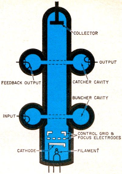
Klystron plate voltage must be accurate and have good regulation for efficiency. Since the output signal is much greater than the input signal applied to the buncher, due to the electron concentration which takes place in the drift space, the klystron may be used as an amplifier. It can also be used as an oscillator by coupling the catcher cavity back to the buncher. While the two-cavity klystron is basic, it is not the only type produced. A single-cavity type, called a reflex klystron, uses the same cavity as both a buncher and catcher; here, a negative voltage is applied to the collector, repelling the electron stream back on itself so that it passes the double-grid assembly both "coming" and "going." More recently, a three-cavity electrostatically focused klystron has been developed. Commercially available klystrons operate at frequencies from a few hundred to over 120,000 mc. (120 gigacycles), delivering output powers from less than a milliwatt (for receiver applications) to many watts (for transmitters). Traveling-Wave Tubes. Utilizing some of the basic operating principles of both magnetrons and klystrons, traveling-wave tubes (or, simply TWT's) may be used both as amplifiers and oscillators. Like the magnetron, these tubes depend on the interaction between moving electrons and a magnetic field, and, like the klystron, they employ the principle of velocity-modulation. The traveling-wave magnetron is one type. Consider the multi-cavity magne-tron in the drawing on page 55. Suppose the circular anode were split at one point and "straightened out." The result would be a multi-cavity anode similar to the tube shown on this page (top). To this we add a plane electrode to serve as a cathode plate, an electron gun, and a collector, plus a focusing magnetic field (not shown) to keep the electron stream projected by the gun from actually touching either the anode or cathode. The anode and plane cathode form a wave guide. If an r.f. signal is introduced at one end, it will travel to the other end. Now, if the velocity of the electron stream is adjusted to match the phase velocity (speed at which a constant phase progresses) of the electromagnetic wave moving down the tuned wave guide, the electron stream will be velocity-modulated and will transfer some of its energy to the traveling wave. The result, then, is that the output wave collected at the far end is stronger than the input signal, thus fulfilling the basic condition for amplification. A different type of TWT consists of an electron gun, a wire helix, and a collector. A tube connects the input and output wave guides at each end of the helix. In operation, a stream of electrons is sent down the axis of the helix and the input signal is fed in. The helix, acting as a coiled transmission line, transmits the input signal to its far end at an axial velocity determined by the ratio of the pitch to the circumference of the helix. If the electron stream velocity matches the traveling wave's axial velocity, there is an interaction between the wave and electrons, transferring energy from the electron stream to the wave and thus amplifying it. Since the currents induced in the helix are displacement currents, the electron stream need not actually touch the helix and hence a strong magnetic field is generally used to focus the electron stream and to keep it from diverging over its relatively long path. The traveling-wave magnetron combines functional principles of traveling-wave tube and a magnetron. Traveling-wave tube provides broadband amplification in the 3000 to 50,000 mc. frequency range. Wave motion in the backward-wave oscillator is in the opposite direction to wave motion in other traveling-wave tubes, but the principle is the same. The backward-wave oscillator tube (or BWO) operates on general principles similar to those employed in conventional TWT's except that the traveling wave moves in a direction opposite to that of the electron stream (hence the name). In one sense, the tube serves to supply its own "input" signal. Sometimes, a strong transverse magnetic field is used to bend the electron stream in a circular path and thus to reduce the overall size of the tube. Modified versions of magnetrons, klystrons, TWT's and BWO's are made by a number of manufacturers under special trade names, such as "Amplitron" and "Stabilotron." Special-Purpose Tubes. In addition to the basic electron tube types we've discussed, the tube "family tree" has one branch which is literally "loaded" with twigs. These are the special-purpose tubes - those types designed for one or more specific functions and, therefore, of limited general application. A prime example is the electronic flash tube used in photographic equipment, essentially a gas-filled triode with a trigger electrode. A mere description of all the various special-purpose tubes would fill a book, so we'll just examine a few representative types. The voltage-regulator (or VR) tube is a diode filled with an inert gas having a specific ionizing potential, such as neon, argon or krypton. In operation, this tube acts like an open circuit until sufficient voltage is applied to ionize its gas. At this point, it "fires" and maintains a constant voltage drop, drawing a greater or lesser current (within its rated limits) as the applied voltage varies. The purpose is to hold the output or resultant voltage constant. The gas-filled regulator has a constant voltage drop between anode and cathode. The gas-filled radiation detector tube depends on ionization of gas by high-velocity atomic particles. Used in radiation detectors, the Geiger counter tube is also a gas-filled diode. Generally, the tube is a thin metal shell with a coaxial wire or rod-like electrode. In use, a high d.c. voltage is applied to the two electrodes. If an alpha or beta particle or a gamma ray enters the tube, the gas is ionized momentarily, permitting conduction to take place and delivering a pulse of current. Each time another radioactive particle enters, the tube delivers another pulse. These pulses can be amplified and used to drive a loudspeaker or headphones or, if preferred, fed to an electronic counting circuit. The number of pulses in a given period of time (that is, the pulse rate) is proportional to the number of radioactive particles or rays which enter the tube, and hence to the intensity of the radioactivity measured. Nixie indicators are gas-filled tubes having cathodes that glow when passing current. There are a variety of indicator tubes, with the simple neon bulb being a prime example. Another type is the Nixie tube. A cold-cathode gas-filled type, this tube is equipped with a number of cathodes, each shaped to represent a numeral from 0 to 9. When an ionizing voltage is applied between one of the cathodes and the common plate, that cathode glows, rendering the numeral visible. Nixies are used as read-out devices in computers and counters. The famous tuning-eye tube is another type of indicator tube. In its basic form, it consists of a cathode, control electrode, and fluorescent screen to which a positive voltage is applied. The electrons leaving the cathode are attracted to the fluorescent target, causing it to glow. When a negative voltage is applied to the control electrode, it repels these electrons, leaving a "shadow" on the target, with the shadow area proportional to the amplitude of the applied d.c. voltage. Sometimes, a tuning-eye type indicator tube and triode are combined in one envelope. Used in computers, counters and similar equipment, the beam-switching tube is made up of a cathode, beam forming and holding spades, shield grids, switching grids, output (target) electrodes, and rod-type permanent magnets. In operation, the electrons emitted by the cathode are formed into a narrow beam by a combination of magnetic and electrostatic fields. This beam is held in a fixed position by the potentials applied to the various electrodes, but can be switched from one target electrode to another, in rotation, by applying suitable voltages to the switching grids. In the beam-switching type of indicator tube, deflector electrodes direct the electron beam to the desired target anode. Such tubes may have 20 or more anodes. Other special-purpose tubes include ionization and thermocouple-type vacuum-gauge tubes; tubes in which one of the control elements is mechanically linked to an external pressure button so that the tube can be used as a mechano-electronic transducer; types with built-in fixed resistors used as ballast tubes; special T-R (transmit-receive) tubes to prevent the application of transmitter power to a receiver when both units share the same antenna system; and many, many other kinds. The Future. Electron tube manufacturers are constantly seeking ways to improve their tubes and to develop new types to meet the needs of equipment designers and manufacturers. Great efforts are being expended in the development of UHF and microwave tubes. Several firms are working on tubes requiring low operating voltages which will be competitive with the transistor. One firm has developed a tube without a filament - it's designed to be used in an environment so hot that the cathode requires no additional heating. And an envelope-less tube has been developed for use in the vacuum of outer space. How will the tube "family tree" branch out in the future? Even an educated guess is likely to be wrong. Only two things are certain: There will be many new types of tubes introduced in the next several years, and the "tree" will keep right on growing!
Posted November 29, 2021 |
|