|
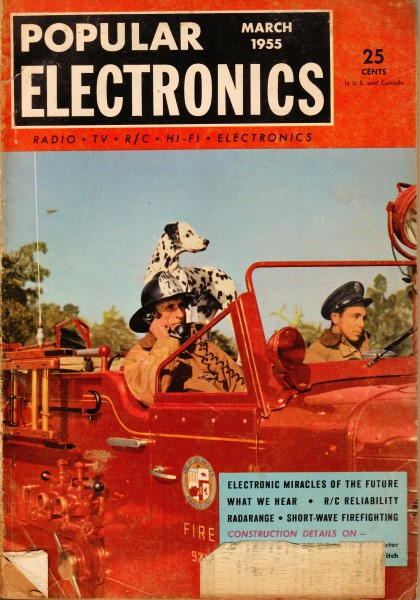
As time marches on and
electronics components get smaller and smaller, there is no just no room to apply
color code markings for values, but in a lot of instances there is not even room
to apply a laser alphanumerical marking (at least not one large enough to be seen
with an unaided eye). This goes for common passive components like capacitors, inductors,
and resistors as well as for integrated circuits, RF couplers and power dividers,
diodes, and transformers. Open your Wi-Fi router and try to find a useful component
designation. Only the largest parts will have anything you can look up on the Internet.
There are ways to hunt down identification for some of the parts, but at least for
R's, L's, and C's, the only way to discover a value without the assistance of a
schematic is to measure it. If you look at older electronics equipment, you will
immediately notice color stripes and/or dots on many components. The tables below,
from a 1955 issue of Popular Electronics magazine, will help you decipher
the meanings for component value, tolerance, temperature coefficients, etc., as
applicable.
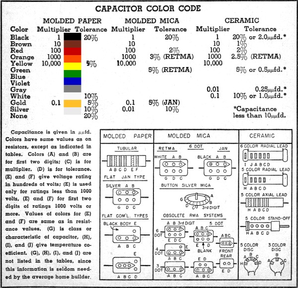
Capacitor Color Code Chart
|
Capacitance is given in µµfd. Colors have the same values as on resistors, except
as indicated in tables. Colors (A) and (B) are for first two digits; (e) is for
multiplier. (D) is for tolerance, (E) and (F) give voltage rating in hundreds of
volts; (E) is used only for ratings less than 1000 volts. (E) and (F) for first
two digits of ratings 1000 volts or more. Values of colors for (E) and (F) are same
as in resistance values. (G) is class or characteristic of capacitor. (H), (I),
and (J) give temperature coefficient. (G), (H), (I), and (J) are not listed in the
tables, since this information is seldom needed by the average home builder.
Related Pages on RF Cafe - Capacitors &
Capacitance Calculations -
Capacitor
Color Codes - Capacitance Conversions -
Capacitor Dielectrics -
Standard Capacitor Values -
Capacitor Vendors -
The Noble Art of De-Coupling
|
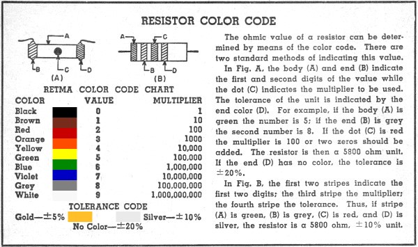
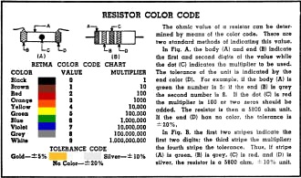
The ohmic value of a resistor can be deter-mined by means of the color code.
There are two standard methods of indicating this value. In Fig. A. the body
(A) and end (B) indicate the first and second digits of the value while the dot
(C) indicates the multiplier to be used. The tolerance of the unit is indicated
by the end color (D). For example. if the body (A) is green the number is 5; if
the end (B) is grey the second number is 8. If the dot (C) is red the multiplier
is 100 or two zeros should be added. The resistor is then a 5800 ohm unit. If the
end (D) has no color. the tolerance is ±20%. In Fig. B. the first two stripes
indicate the first two digits; the third stripe the multiplier: the fourth stripe
the tolerance. Thus, if stripe (A) is green, (B) is grey, (e) is red, and (D) is
silver. the resistor is a 5800 ohm, ± 10% unit.
|
Posted January 11/2023
(updated from original
post on 4/21/2013)
|