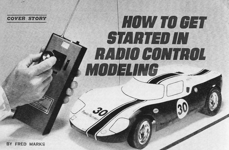
How to Get Started in Radio Control Modeling
|
|
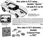
Here is an advertisement for the Heathkit R/C car and radio system featured in this article. Radio control hobbyists realized a huge technology advance with the introduction of solid state proportional control systems that began appearing in the late 1960s. Prior to then, most R/C systems used vacuum tubes and their accompanying large, heavy batteries. Size and weight was not too big of a deal for the transmitter, but both those factors for an airborne receiver significantly impacted airplane design and performance. The new systems enabled smaller, lighter weight aircraft that not only cost less, but flew better. Of course other forms of R/C modeling like boats and cars also benefitted from the advances, but weight and size was not as much of an issue (other than for convenience). Incremental improvements in electronic components and packaging helped improve solid state systems through highly integrated circuits for modulation / demodulation function, servos motor power and efficiency, RF sections, and human interface elements like gimbal sticks and programmability. An FCC mandate changing the system bandwidth from 40 MHz to 20 MHz doubled the available unique frequencies (channels) in the popular 72 MHz (model aircraft only) and 75 MHz (cars & boats only) unlicensed bands. Ham operators can opt for 50 MHz and 53 MHz operation. There are some 27 MHz and 49 MHz bands available, but they are highly subject to Citizens Band (CB) radio interference. Today, nearly all radio control systems operate in the 2.4 GHz ISM band and use frequency hopping (FHSS) and direct sequence (DSSS) spread spectrum mod/demod techniques. Most receivers employ an articulating dual antenna arrangement that produces out-of-sight range with almost total immunity to interference. Whereas prior to spread spectrum, only one transmitter could operate at a time on a given channel. In fact, a "frequency board" was commonly erected at a flying field whereby a person could only turn on his transmitter if he had gotten a frequency-identifying marker to clip onto his antenna. That prevented someone else from inadvertently (aka "stupidly") turning on his transmitter and causing another person's model to crash or causing harm in the pit area. Channel assignment meant no more than 50 models could be in the air at a time, but even with that many channels available, you could almost be assured of someone else showing up at the flying field with your frequency. FHSS / DSSS systems have totally eliminated that issue. See also "How Radio-Control Systems Work" in the May 1974 Popular Electronics issue. If you are interested in radio control modeling, you might enjoy looking around my www.AirplanesAndRockets.com hobby website. Solid-state designs spur growth of exciting hobby
By Fred Marks It is almost impossible to convey the full excitement of radio control (R/C) modeling to anyone who has never been at the controls. While some of the glamour and excitement of the hobby are almost certain to rub off on the "audience" at a modeling meet, the ultimate thrill is reserved for the hobbyist at the transmitter controls as he maneuvers his model airplane, racing car, or boat over an intricate course. Operating a model by radio control is similar to - yet vastly different from - operating a full-size vehicle. The major difference, of course, is that the model under your control is always at a distance from you. Even so, you can almost feel the G forces acting on it. R/C modeling is one hobby that lets you exercise maximum creativity, manual dexterity, and competitive spirit. And you will learn a great deal about electronics, mechanics, and physics while having fun. How It Started. Radio control for modelers dates back to the 1930's. By todays standards, the electronic gear that the pioneers of the hobby used was primitive and massive. Back then, you needed a ham license to operate R/C equipment, which limited the number of hobbyists to a relative few.
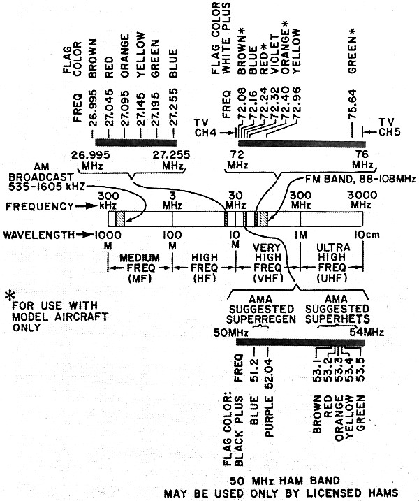
Three bands of frequencies have been allotted for use by hobbyists in radio control. Flag colors designate channel being used. In 1952, the FCC established the Citizens Radio Service, permitting almost anyone who wanted one to obtain a radio operator's (CB) license. No code or written test was required for the new license, and many people who did not feel it was worth it to study code and theory for ham licensing exams clamored for the new CB license. Some wanted it for voice communication; prospective R/C hobbyists wanted it to get into modeling. With the opening of the Citizens Band, R/C modeling started to grow. By 1958, in fact, there were as many as 50 modelers who met at flying fields or boat sites During this period, the equipment remained relatively unchanged. Furthermore, all modelers had to share primarily 27.255 MHz, a frequency also used by voice-communicating CB'ers, taxicabs, and traffic departments for controlling signal lights. The modeler's maximum transmitter power was limited to an input of 5 watts, but other services on the same frequency were permitted up to several hundred watts. Through the efforts of the Academy of Model Aeronautics (AMA), the national association of model aviation, hobbyists were permitted, commencing September 11, 1958, to operate on five new Class C frequencies: 26.995, 27.045, 27.095, 27.145, and 27.195 MHz. The new frequencies and the development of more selective receivers bought interference problems to a temporary halt. Operating on the new frequencies offered a greater advantage. Selectivity made the new receivers immune to transmitters on other frequencies. Hence, as many as six models could be controlled simultaneously. At large meets, flight lines actually formed for each frequency. Meanwhile, the introduction of the transistor in the mid-1950's gave a tremendous boost to R/C modeling. Small and lightweight, the transistor considerably reduced the demands placed on battery supplies in both transmitters and receivers, which in turn, reduced the size and weight of the batteries themselves. As transistors replaced tubes, R/C equipment became miniaturized to the point where transmitters were, for the first time, small enough to be hand-held. And transistor circuits proved to be much more reliable than tube-circuit counterparts.
A typical 3·channel transmitter using conventional cells rather than rechargeable.
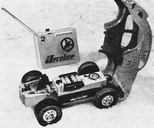
Simple projects like a converted Baja Bug are fine first projects for learning basics.
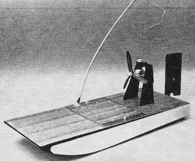
Another simple first project is an airboat. It is ideal for use on local city park ponds. An Era of Change. By 1963, interference had again become a serious problem to R/C modelers. Class D CB'ers had crowded the airwaves, and there were now more modelers than there was spectrum space to meet their needs. It was common at many flying fields for a strong signal from a passing mobile CB rig to completely disrupt operations. An organized effort, begun in 1963 and led by officers of the AMA, culminated in 1966 with the FCC's approving five new frequencies for R/C operation: 72.08, 72.24, 72.40, 72.96, and 75.64 MHz. In 1971, 72.16 and 72.32 MHz were added to the list. The present frequencies on which R/C modeling is permitted are shown in the frequency spectrum diagram. Six frequencies are available in the 27-MHz CB band, seven in the 72-76-MHz band (four for model aircraft use only), and seven in the 50-54-MHz 6-meter ham band. If all available frequencies were in simultaneous use at a given site, as many as 20 models could be active. On the 27-MHz band, excluding 27.255 MHz, a maximum of 3 watts input to the final amplifier in the transmitter is permitted, and crystals must be ground to a 0.01-percent tolerance. On 27.255 MHz, 3 to 5 watts input, also 30 watts, is permitted, provided that the crystal is ground to a tolerance of 0.005 percent. The 27.255-MHz frequency, however, is seldom used by modelers because of the severity of the interference often encountered. A 3-watt input for R/C transmitters is rather high. For practical purposes, a 1-watt input would be typical, while 0.5 watt is quite acceptable. Some transmitters are rated at 100 mW or less input. They require no station license, but are subject to the same tolerance and modulation requirements of the higher-powered transmitters. Requirements for Operating R/C. Operating R/C equipment is a privilege granted the operator by the citizens of this country in that (a) one must properly share the radio spectrum and (b) be familiar with and observe the applicable regulations. Transmitters rated at over 100 mW may be operated only by those who have secured an FCC license. Any citizen of the U.S. who is 12 years of age or older can qualify for this non-ham station license. To obtain a license for the non-ham bands, you must familiarize yourself with Volume VI, Part 95 of the FCC Rules and Regulations (obtainable from: Superintendent of Documents, Government Printing Office, Washington, DC 20402 for $1.25) pertaining to the Citizens Radio Service. Then fill out FCC Form 505 (get it from: Federal Communications Commission, Washington, DC 20544) and mail it with a check or money order for $20 to: Federal Communications Commission, Gettysburg, PA 17325. The $20 fee covers station licensing for five years. The station license covers all transmitters listed by you on Form 505 and bears your call letters. The ham license required for R/C operation on 50 to 54 MHz offers the advantage of being able to become active in other ham communications. You must pass a 5-wpm code test and a simple written test. Try to get your technician ticket at the outset. A novice ticket is good for only two years, after which you must pass the technician test to remain a ham. Summing Up. Many hobby shops stock everything you need for R/C modeling. Your investment for electronic gear can be as low as $50 for the most basic single-channel pulse-type system to several hundred dollars for the most sophisticated multi-channel digital-proportional system. For more information about R/C gear, you might write to the companies listed in the accompanying table. We are planning additional coverage of various R/C systems and how they work in a future issue. Watch for it. How We Tested Heath's 3- or 4-Channel Digital Propo R/C SystemR/C Equipment Manufacturers Ace Radio Control, 203 W. 19 St., Higginsville, MO 64037 Citizenship Radio Co., P. O. Box 297, Westfield, IN 46074 EK Products, Inc., 3233 W. Euless Blvd., Hurst, TX 76053 Futaba, 1124 E. Amo Blvd., Carson, CA 90746 Heath Co., Benton Harbor, MI 49022 Model Rectifier Corp., 2500 Woodbridge Ave., Edison, NJ 08817 Orbit Electronics, 312 Gillette St., Santa Ana, CA 92705 Pro-Line Electronics, Inc., 1213 E. Glendale Ave., Phoenix, AZ 85011 Royal Electronics Corp., 2119 S. Hudson St., Denver, CO 80222 RS Systems, 2407 S. Broadway, Santa Ana, CA 90707 World Engines, Inc., 8960 Rossash Ave., Cincinnati, OH 45326 To present a full report on R/C modeling, the staff of Popular Electronics built and tested its own car and control system. We used kits made by the Heath Company, which included a Model GDA-1057-1 3·channel transmitter, Model GDA-1057-2 receiver, Model GDA-405-3 receiver battery, and two Model GDA-405-44 miniature servos. (These items have a special system price of $150, though, if purchased separately, the total cost would be $170.) For future use, we added an optional Model GDA-1057-4 fourth channel ($20) and two more miniature servos ($25 each). To use with our radio control system, we decided on a model racing car, which is probably the easiest thing to control and can be operated under less favorable circumstances than a boat or a plane. We used the now discontinued Heath "Spectre" racing car in which we installed a locally obtained $25 glow-plug engine. The R/C System. The transmitter is basically a three-channel digital-proportional unit that supplies 500 milliwatts to the input of the power amplifier. A joy stick controls the encoding for channels 1 and 2 (left and right turning on channel 1 with nothing on channel 2, or, for a model plane, elevator and rudder), both of which are equipped with secondary trim-pot tabs. The channel·3 control (throttle) is a similar trim-pot tab located on the right side of the transmitter case, which is the size of a walkie-talkie. The stick is spring-loaded on both channels so that it returns to its center (neutral) position. The throttle control stays where it is set. When converting to a four-channel system for model planes, the control for channel 4 (rudder, with channel 2 becoming aileron) goes on top of the stick. The only other external control is the power switch located on top of the case near the telescoping whip antenna. The switch is equipped with a lock-off tab that slips into place to prevent accidental turn-on. The state of the battery charge is indicated by a small meter on the front of the case just above the stick assembly. The transmitter (and receiver) operates on one frequency, which can be any one of 17 in the 27-, 50-, and 72-MHz bands. We chose our transmitter to operate on 26.995 MHz.
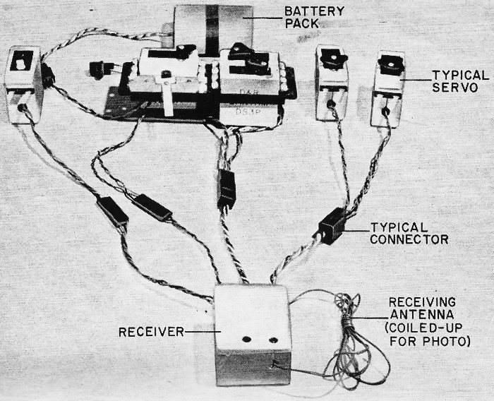
Airborne control package provides one to eight channels depending on transmitter used.
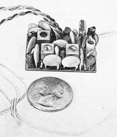
Tiny Ace R/C Microgem pulse receiver is not very much bigger than an ordinary quarter. The receiver measures 2 17/64" by 1 3/16" by 1 5/32" and weighs 2.5 oz, exclusive of the battery pack. Its i-f is 453 kHz, while its sensitivity is 5 microvolts or better. Operating from its 4.8·volt nickel-cadmium battery pack while driving two miniature servos, the current drain is roughly 6 mA, providing four hours of service from a full charge. Three ceramic filters are used in the i-f section. Each of the miniature servos measures 2 17/32" by 1 5/8" by 7/8" and weighs 1.75 oz. They will accept a pulse 1 to 2 ms wide at 4 volts peak-to-peak. Thrust is 4 lb, minimum; travel time is 0.6 second; linear output travel is 1/2" end to end; and rotary output travel is 90°. The mechanical outputs include one rotary arm, one wheel, and two linear racks. Assembling the transmitter was a straightforward job, simplified by the fact that the transmitter section comes fully assembled and pre-aligned to the frequency specified. Assembly time was about nine hours. The receiver and servos employ very small PC boards, the former containing two closely packed assemblies that require careful component mounting and lead soldering. In neither case was assembly particularly difficult, and the servos went together quickly because most of the electronic functions are performed by a single IC in each. Assembly time for the receiver (including installation of fourth-channel option) was about 5 1/2 hours, while only 1 1/2 hours are required for each of the servos. (Note: the battery charger was assembled with the transmitter. It simultaneously charges the nickel-cadmium batteries for both the transmitter and receiver.) How It Performed. The combination of Heath car, engine and R/C system proved to be an excellent choice for us. After tuning the system for the proper responses at maximum range, we were ready for our first run. We found an immediate snag; the new battery we had bought the day before must have stood too long on the shelf because it would not start the engine. But once it was replaced by a fresh unit, the engine turned over with a roar and spewed out billows of bluish smoke (normal for a glow-plug engine). At first we operated the controls timidly. For example, we opened the throttle just enough for the racing car to move at about a normal walking pace while controlling left-right steering in a slalom-like pattern. A few minutes of this, and we were ready for more speed. But owing to our lead fist, we advanced the throttle to almost wide open. There was an immediate increase in decibels as the engine wound out and the car almost flew away from us. Just a touch on the steering was enough to send it spinning out. Then when we attempted to throttle down and apply the brake a second snag appeared: the car slowed too gradually for proper operation. An inspection revealed that the brake had torn loose from its lever. The next weekend, after soldering the brake back onto its lever, the car and R/C system performed flawlessly. Another mishap occurred when we forgot to lubricate the axle between runs; the axle seized in its bushings. Fortunately, after it cooled and was lubricated, we found that no permanent damage was done. We now remember to obey the lubrication caution noted in the Heath manual. Owing to the car's mass, low center of gravity, and fast steering response, the Spectre stayed glued to the racing course at speed. Getting used to the light touch required on the steering at speed and to switch perspectives as the car is coming toward us took only about a half hour. Now that we have many hours of operation behind us, we feel confident enough to entertain the idea of entering some races.
Posted March 8, 2024 |
|