The Magnetic Reed Switch
|
|
According to authors Neal Jensen and Alexander Burawa, magnetic reed switches were developed as recently as 1940 at the Bell Telephone Laboratories to replace the expensive and power-hungry traditional solenoid-based relays. Development cost was reportedly $100 million ($750M in 2018 dollars). I would have guessed reed switches were invented half a century earlier, given how fundamental their concept and construction is. Maybe there was no perceived urgency back when power efficiency was not such a big concern given the wattage used by vacuum tube circuits that often employed the relays. As in increasing number of homes and businesses had telephones installed and party lines (shared by two or more users) gave way to private lines, the physical space needed for switching stations was added to cost and power consumption concerns. World's Most-Sensitive Low-Cost Relay
Have you ever decided to build a project only to find that an expensive or hard-to-get sensitive relay was required? If you didn't forget the whole idea right then and there, you probably worked up an "easy-way-out" solution to your relay problem - probably adding an extra amplifying stage to develop enough power to energize a general-purpose relay. But all you would really accomplish with such a solution would be to cut down the cost of the relay and add the cost of the components needed for the extra circuit. There is a far simpler solution to the problem, but one that many hobbyists and experimenters often overlook. Instead of using a general-purpose relay, you can substitute a magnetic reed switch. With a reed switch, you don't sacrifice sensitivity for price. You can realize up to 90% savings by using a reed switch instead of a conventional relay. Most experimenters will question the suitability of reed switches in applications that call for a general-purpose relay - regardless of sensitivity. In this article the two devices will be compared, and you can make your own judgment. You will find that the reed switch - though a boon to electronics - will not obsolete the relay in all switching applications, just as the transistor has yet to replace all electron tubes. Magnetic reed switches are second-generation relay-type switching devices. They were invented at the Bell Telephone Laboratories in 1940 to reduce the costs of maintaining and replacing conventional relays and to meet the needs for higher efficiency and greater sensitivity for switching devices used in complex telephone systems. Partly because they were invented by Bell Telephone and partly because they combined high speed and uniform performance over long periods of time, reed switches played their first major role in telecommunications equipment. But because the reed switch is sensitive, compact, lightweight, and costs only a fraction of the price of a relay exhibiting the same characteristics, its use has extended to business, industry, and now to the experimenter. Relays are comparatively heavy, bulky affairs. Because relay contacts are often open to the surrounding air - sometimes even corrosive atmospheres - periodic servicing is required to remove dirt and corrosion. By the nature of its construction, the relay is a low-efficiency device, generally insensitive to small energizing currents.
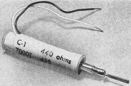
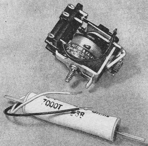
When a reed switch is used in place of a conventional relay, a solenoid is needed to close the reeds by means of electrical energy. The reed switch must be inserted in hollow core of solenoid. Conversely, the magnetic reed switch is compact and lightweight. Its contacts, sealed in an inert-gas-filled glass tube, never need servicing. And the inert gas in the tube retards arcing between the contacts - another problem with open relays. Sensitivity not possible with even the best of conventional relays is a characteristic of a reed switch.* For example, it is possible to close a reed switch with less than 3 mA at 6 volts. A costly relay would have to be custom-made to provide this sensitivity and current handling (at the contacts) capacity. Relays are low-speed switching devices, almost totally inadequate at switching speeds exceeding approximately 150 open-and-close actions per second. Reed switches, on the other hand, are high-speed devices, usable at switching frequencies up to 500 open-and-close operations per second. The average contact make-or-break response time of a reed switch is on the order of 1 millisecond. The useful life of a typical reed switch will generally exceed 10-million operations. In circuits where current flows only after the contacts are closed, this figure can be as high as 500-million operations. No relay yet designed can compare with these figures. Reed switches, of course, have certain disadvantages that make them unsuitable for some applications. Presently available reed switches can handle low to moderate power loads, up to about 50 voltamperes. Reed switches are also limited to a simple on/off action. Complex switching arrangements, however, can be obtained by "ganging" several reed switches and operating them with a common energizing power source. Unlike some relays that can be energized from either an a.c. or a d.c. source, reed switches are restricted to d.c. sources only. If an a.c. source were used, the reed switch would open and close in step with the frequency of the applied power. The most readily apparent difference between reed switches and conventional relays is in their respective construction (see photo at right). There is a significant difference in the proximity and orientation of the energizing solenoids. The relay's movable contacts are spring-returned to their passive position when no power is applied to the energizing solenoid. The only spring action in the reed switch is the slight amount built into the reeds. What does this difference in construction mean in terms of sensitivity? In a nutshell, it means all the difference in the world. The relay action depends on the electromagnetic field (from one end of the solenoid) being strong enough to overcome the tension of the spring. This is a waste of electromagnetic energy. The contacts of the reed switch form the core of the energizing solenoid and are at the center of the electromagnetic field.
Different methods of construction used in conventional relay (top) and reed relay (bottom) account for wide variations in sensitivity between devices. Since the energizing solenoid extends from one end of the reed switch to the other end, an interesting phenomenon takes place when the solenoid is connected to a power source. The contacts become separate magnets with opposing magnetic poles. These low mass contacts, overlapping and closely spaced, are instantly attracted to each other. The density and strength of the magnetic field running through the center of the solenoid is considerably greater than that around the outside of the solenoid, so less power is required to close the reed-switch contacts than is required to close the relay's contacts - considerably less. Almost all the energizing current flowing through the solenoid is used to close the contacts of the reed switch, while less than 50% is used in the relay. Where only a few milliamps of current are available for closing the contacts of a reed switch, a permanent magnet is often used to increase sensitivity. The permanent magnet biases the reed switch in such a way that its field and the field of the solenoid aid each other. As a result, the amount of current needed to close the contacts can be reduced to a level determined by the proximity of the permanent biasing magnet to the contacts of the reed switch. In present-day electronics, where transistors are the building blocks for circuit designs and design concepts, sensitivity is a key feature. Transistors - generally low power devices when compared with vacuum tubes - require the use of high-sensitivity switching devices for proper switching action. Relays that are designed to energize with 4-mA drain on the circuit generally cost more than $10, whereas a reed switch, designed to operate at 2 mA, need not cost more than $2 - if the energizing coil is home-wound. Perhaps the most important role the reed switch has played to date is in the "No. 1 Electronic Switching System"** (ESS) developed by the Bell Telephone Laboratories at a cost of some $100-million for research alone. The No.1 ESS is the world's most advanced switching system for telephone communications, and because of its high-speed/high-reliability requirements, reed switches are being used almost exclusively in place of relays. The No. 1 ESS is so successful that over the next three decades it should become the telephone equipment standard throughout the United States. Solid-state devices and magnetic reed switches have made this new system possible. The results obtained by Bell Telephone are just as easily applicable to your next relay project-if you use a reed switch. Immediately following are details for winding your own solenoid for a popular model of reed switch. * The sensitivity of a reed switch depends on the characteristics of its energizing solenoid and whether or not a permanent magnet is used to bias the switch - in much the same manner as biasing is used in an amplifier circuit. ** An article that goes into further detail about tile "No.1 ESS" appeared in the January, 1965, issue of Popular Electronics (The Great Immortal Machine, page 69).
Posted October 5, 2018 |
|