Mac's Service Shop: Leakage Current Testing and Using Square Waves
|
|
Long before any one was overly concerned with relatively paltry electrostatic discharge (ESD) current causing damage to semiconductor components, there was a need to model the human body's resistance to current flow due to electric shock concerns. Even with a huge number of people being severely shocked and/or killed due to exposure to potentially lethal voltage levels, it was not until the late 1960s that OSHA and the National Electric Code began requiring exposed metal components (chassis, switches, etc.) to have a safety ground connection. Popular Electronics ran an article titled "Shocking But True" in the August 1959 issue dealing with the subject. Many older radio and TV chassis would be "hot" if the 2-pronged plug was inserted the wrong way into the wall receptacle, so touching any metal component (even an exposed tuning knob or volume control shaft) would light you up. The situation was even worse in the early days of AC electric service because in many cases there was no earth ground established at the service entrance, so both conductors were floating and could be at any voltage between ±170 volts (120 * √2) wrt ground. Today's formal human body model (HBM, latest version are JS-001-2017, IEC 61000-4-2, and MIL-STD-883K) ESD test source consists of a100 pF capacitor in series with a 1,500 Ω resistor. The capacitor is charged to the specified voltage and then it is discharged through the resistor into the device under test (DUT). Mac's Service Shop: Leakage Current Testing and Using Square Waves By John T. Frye, W9EGV, KHD4167
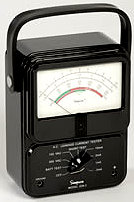
Barney came skipping through the front door of the service shop and gently laid a long-stemmed yellow tulip atop Matilda's typewriter; then without a word to the astonished office girl, he went on back to the service department, where he found Mac, his employer, examining two new instruments resting on the service bench. The larger, at first glance, looked like a conventional Bakelite-cased VOM, but lettering on the front revealed it was a "Simpson Model 229 Leakage Current Tester." The range switch had positions designated: OFF, BATT TEST, 150 VAC, SHORT TEST, 10mA, 3mA, 1mA and 0.3mA. There were matching scales on the meter face. "What do you do with that odd-ball meter?" Barney asked.
Simpson 229-2 AC Leakage Current Tester - still available from Simpson. "You measure the amount of 60-Hz current that flows from an electrical line conductor to the metal exterior of an electrical device and thence through an electrical simulation of a human body to an earth ground. Such a dangerous current flows when there is a conductive path, resistive or capacitive, between the hot wire of the device and the case and when the person using the electric drill, hedge-clipper, sander, or what have you simultaneously touches the case and a grounded object. "This current flows because one side of the 117-volt, single-phase, two-wire line is grounded at the pole transformer and again at the electrical entrance to the building. That means you do not have to touch both wires simultaneously to be shocked. All you have to do is to establish a return circuit between the 'hot' wire and the earth. You can prove this to yourself by connecting a 117-volt bulb between the hot wire and a water pipe. The bulb will burn almost as brightly as if it were connected across both wires of the line. It will also burn, although usually less brightly, if a poor ground such as a metal stake driven into the earth is used. "The American National Standards Institute suggests the circuit I've drawn there on the blackboard to test for leakage current. As you can see, one lead of a meter whose characteristics correspond to their specified standards - and this one does - is connected to the grounded neutral conductor. The other meter lead is used to probe the case or any exposed metal parts of the appliance being tested. The ac line is connected to the appliance through switches S1 and S2. All switches on the appliance are turned on. "With S1 open, only the hot wire is connected to the electrical circuit, and the return path from the case to the grounded lead is through the meter. With S1 closed, power is applied normally to the device being tested, but leakage current reaching the case still returns to ground through the meter because the ground pin socket of the 2-pole, 3-wire grounding type socket is left open for these tests; otherwise any leakage current would bypass the meter. S2 reverses the hot and ground wire connections to the appliance. Motor operated appliances are tested under 'no load' conditions. Heating appliances are tested at maximum heat setting of controls."
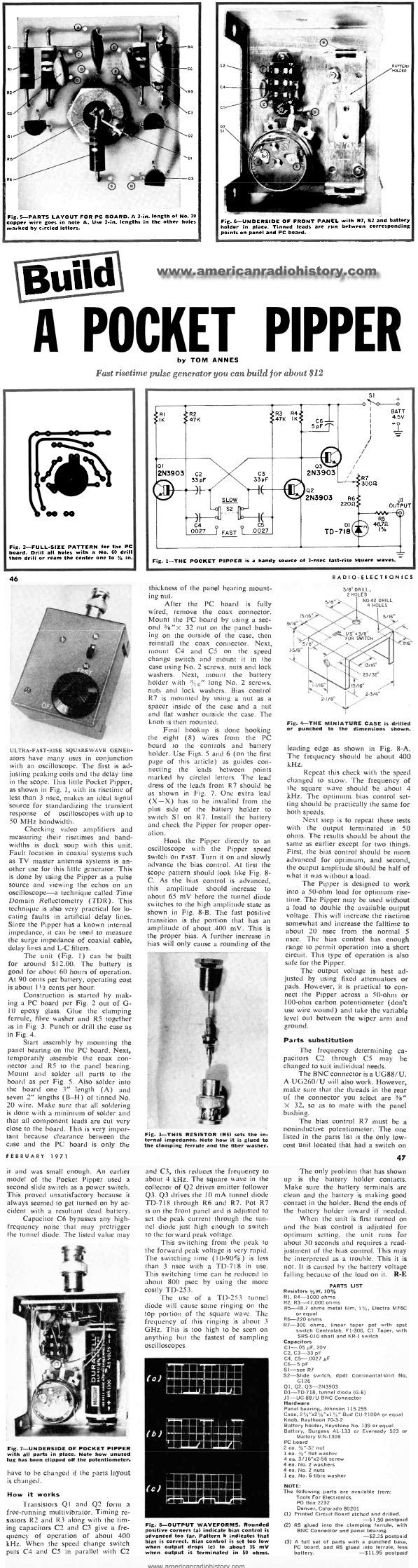
Circuit suggested by American National Standards to check leakage current. "Why reverse the line cord connections?" "Because, if the leakage path happened to be between the grounded lead and the case, no leakage current would be present; but when the line plug was reversed, the path would be between the hot lead and the case and leakage current would appear. Take that signal tracer of ours. With S2 in one position, no leakage current is seen; but in the other position, 2.25 mA of current passes from the case through the meter." "A partial short from one end of the transformer primary to the core, huh?" "No, although that could happen. The leakage current path is through an 0.05 capacitor from one side of the line to the chassis, which is bolted to the case. The reactance of this capacitor at 60 Hz is about 53,000 ohms, which will pass almost precisely 2.25 mA of current when subjected to 117 volts, as happens when the side of the line to which the capacitor is connected is hot." Resistance of Body. "You say that meter simulates the resistance of the human body to electrical current. How does it do that?" "By presenting a terminal impedance of 1500 ohms noninductive resistance shunted by 0.15 μF of capacitance. This is the experimentally determined 50 percentile threshold-of-perception-curve value determined by Charles F. Dalziel and others for an average human being in an average environment of temperature, pressure, humidity, etc., when subjected to small ac or dc currents. Remember that name of C.F. Dalziel. You're going to hear much more about him when we talk about the biological effects of electric shock in the near future. But for now, remember the impedance of the human body to electrical current can vary tremendously from this value under non-average conditions. Also health and other conditions can affect the individual's tolerance to electric shock. That's why the maximum leakage current for appliances is set by the ANSI at only 0.5 mA, although most human beings cannot feel even the faintest tingle of electricity until the current is twice this value. The Underwriters' Laboratories feel that this 0.5-mA value of leakage is not likely to produce such adverse effects as ventricular fibrillation, inability to let go of a current-carrying device, or an involuntary reaction which can result in in-jury from secondary causes (e. g. fall from a ladder, spill hot liquids, etc.)" "Then why does that meter have all those current ranges?" "So it can be used to detect everything from a direct conductor-to-case short circuit to very small leakage currents produced by damp insulation or carbon dust paths. Note this instrument is designed to perform one specific job: to measure leakage currents of appliances in accordance with American National Standard specifications. We're going to use it to test all our instruments and electrically operated tools for leakage on a routine basis and to check every set we work on to make sure it is safe for the customer to use. I suggest you take it home with you and check all your tools and all the appliances in your mother's kitchen: refrigerator, dishwasher, toaster, mixer, blender, etc. After you do you'll probably conclude as I have that only a careless idiot employs a cheater plug so he can use his three-wire hedge clipper ungrounded with a two-wire extension cord. He's usually asking for it." What's a Pipper? Barney didn't answer. He had picked up the other smaller instrument from the bench and was examining it curiously. It was a little tan-colored metal box about 2 3/4" X 2" X 1 1/2" with a BNC connector sticking out one end and a control knob and a slide switch on top. One switch position was marked FAST and the other SLOW. "Who is 'TFE' and what is a 'PP-1A'?" Barney read from the little case. "TFE is the manufacturer of that little gem. The letters stand for 'Tools for Electronics,' P.O. Box 2232, Denver, Colorado 80201. The PP-1A tells you that is a 1A Model of the Pocket Pipper" Mac explained with an anticipatory grin. "A pocket what?" Barney asked incredulously. "Pipper. Actually it's a miniaturized, sophisticated, battery-powered, fast rise-time step generator that puts out pulses of stepped voltage with repetition rates of either 2 kHz or 200 kHz. Open circuit output voltage is about 500 millivolts, which falls to about 2/3 this value when working into the output impedance of 50 ohms. But listen to this: the rise time of that stepped voltage is less than 2 ns when working into a 50-ohm load, the following flattop is free of overshoot and ringing, and the fall time is about 5 ns. When working into an open circuit, the rise time only increases to about 3 ns while the fall time increases to about 20 ns. The open circuit rise and fall times cannot be measured exactly because scopes with sufficient bandwidth to measure them have 50-ohm inputs." "What on earth is inside that little box?" "A few ordinary components and some extraordinary ingenuity. Two transistors are used to form a free-running multivibrator. The square wave output at the collector of one of these drives another transistor as an emitter follower. The emitter load of this transistor is a tunnel diode. Now you will recall that a tunnel diode can be biased so that only a very small change in applied voltage will switch it with great rapidity from a high-voltage to a low-voltage state, and vice versa. The control on top of the Pocket Pipper is used to adjust the bias to that condition. Then the square wave from the multivibrator feeding through the emitter follower triggers the tunnel diode back and forth between the high and low voltage states and produces the square-wave-like waveform. But let me show you." Mac slipped a BNC connector carrying about three inches of coax into the Pocket Pipper connector and clipped the leads of the bench scope to the conductor and shield of the coax. He adjusted the scope sensitivity for 100 millivolts/cm and the sweep for 100 microseconds/cm. With the slide switch of the PP-1A in the SLOW position, he turned the control knob clockwise from the OFF position. A couple of cycles of a squarewave-like trace, about 1/2 cm high, appeared on the scope. As Mac advanced the control, the trace suddenly jumped up to a height of more than 5 cm. But now only the horizontal lines marking the tops and bottoms of the square waves could be seen clearly. The bottom lines had curious little up-and-to-the-right hooks on their right ends. Only by advancing the brightness away beyond normal could the vertical rise and fall lines be made out dimly. "Those little hooks on the bottom lines show the increase in the triggering voltage on the tunnel diode just before it switches, "Mac explained. They're not involved in the rise time that's defined as the time it takes a stepped voltage to increase from 10% to 90% of the final value. Now let's look at the 200-kHz output." He readjusted the scope sweep to 1μs/cm and switched the Pocket Pipper to FAST. "Oh, oh!" Barney exclaimed. "The waveform's not so good on that speed. Look at the overshoot and ringing." Sure enough, there was about 7 or 8% overshoot of the leading edges of the square waves and a definite wrinkling of the first part of the horizontal lines. Scope Makes Difference. "That's what I thought until I got suspicious and had a friend take a look at the output of the PP-1A on his Tektronix 547/1A1 scope," Mac said. "Not a trace of overshoot or ringing appeared on it at the FAST speed. The vertical amplifier of our scope simply isn't up to handling a 200-kHz stepped voltage with that fast a rise time without distorting it." "Why not? Our scope has a bandwidth out to 5 MHz." "The trouble lies in how the vertical amplifier response tapers off on the high end. Our vertical amplifier falls off too abruptly because the high end has been overcompensated by propping it up with peaking circuits. Ideally, the response of an amplifier on the high end should follow a Gaussian curve in which the response at twice the 3-dB down frequency is only down 12 dB. It's a smoothly tapering curve like this," Mac said, illustrating with a hand wave. "Why, Mac, I didn't think you'd noticed my figure!" Matilda said from the doorway where she was striking her best starlet pose, leaning hack against the jamb, her back-flung head cradled in her hand, lips parted, and holding the stem of the yellow tulip between her teeth. "Back to your typewriter, wench!" Mac said, getting red in the face. "It's getting so a man can't talk sense around here. Anyway, Barney, I've long wanted a really fast rise time generator we can use to test, for example, video amplifiers for bandwidth, rise time, and transient response. Our old square wave generator is perfectly adequate for most of our requirements, but its rise time of 2 microseconds is too slow to trigger transients in extended-range amplifiers. Still I can't afford to put $500 or so into a fast rise time pulse generator we need only occasionally. But this little gem costs only $12.95 in kit form and will serve our needs handily. Why are you grinning like a Chessy cat?" he broke off. "I was just thinking that now you're not going to be happy until you get a scope that can keep pace with that Pipper." Mac tried to scowl but couldn't quite manage it. "Some people around here are getting just a little too smart," he growled.
Posted November 24, 2017 Mac's Radio Service Shop Episodes on RF Cafe This series of instructive technodrama™ stories was the brainchild of none other than John T. Frye, creator of the Carl and Jerry series that ran in Popular Electronics for many years. "Mac's Radio Service Shop" began life in April 1948 in Radio News magazine (which later became Radio & Television News, then Electronics World), and changed its name to simply "Mac's Service Shop" until the final episode was published in a 1977 Popular Electronics magazine. "Mac" is electronics repair shop owner Mac McGregor, and Barney Jameson his his eager, if not somewhat naive, technician assistant. "Lessons" are taught in story format with dialogs between Mac and Barney.
|
|

 April was never more welcome. The winter had been
long and cold and bitter, filled with natural and man-made disasters; but now it was
over and spring had returned just as, mercifully, it always does.
April was never more welcome. The winter had been
long and cold and bitter, filled with natural and man-made disasters; but now it was
over and spring had returned just as, mercifully, it always does.