Lissajous Had a Figure for It
|
|
Old sci-fi movies were famous for displaying Lissajous patterns on oscilloscopes in hopes of portraying a futuristic look. The first time I hooked up signals to the x and y axes of a scope and played around with the frequencies and amplitudes, I was mesmerized by the patterns and the fact that it was me creating them. Of course that was 30-something years ago when I was first getting into electronics and electricity, but even today it's a cool thing to do. In a typical, male-dominated, Chauvinistic manner, this article from the March 1957 edition of Popular Electronics magazine delves into the subject of Lissajous patterns. The author dares to compares men's attraction to curvaceous o-scope figures to a similar attraction to curvaceous women. Can you imagine the hateful feedback the editor of a current magazine would receive if something like this slipped past the proofreading crew? Of course, it's still OK to denigrate men in any way deemed necessary to spice up an article, but don't dare kid around with women! The NOW crowd will screech a banshee's fit and demand a public apology - and, of course, a large donation to the NOW fund. Lissajous Had a Figure for It  By Howard Burgess By Howard Burgess
Century-old light pattern now serves as electronic yardstick Men are traditionally attracted by figures with curves. A certain Frenchman named Lissajous, who lived around 1855, was no exception. He became an exception when he found that he could control these "figures with curves" in a dark room. He discovered that light reflected from two flat, rapidly rotating mirrors formed simple wave patterns when projected upon a screen.
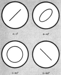
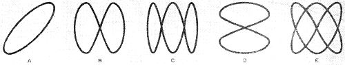
Fig. 1 - Lissajous patterns representing phase relationships between two 60-cycle currents.
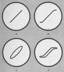
This discovery set in motion a chain of developments culminating in the modern oscilloscope. Lissajous patterns on the oscilloscope screen measure sound frequencies or the rotary speed of a motor, tell whether a transmitter is multiplying frequency properly, check phase shift and distortion in hi-fi equipment, calibrate audio signal generators, and do many other jobs. The light source for Lissajous' mirror-generated patterns was a simple candle. In place of a candle, the modern oscilloscope contains an electron gun in the narrow neck of the tube. This gun shoots about 6,000,000,000 electrons per second in a concentrated high-velocity beam toward the face of the tube. When the impact of this beam strikes the chemically coated face of the tube, it converts its energy into light, forming a small luminous dot. Basic Traces. In its travel toward the tube screen, the electron beam must pass between two separate pairs of deflection plates capable of bending the path of travel. These correspond in their action to Lissajous' mirrors. An electrical signal or voltage applied to one set of the plates bends the beam up or down; a signal applied to the other set of plates bends the beam to the left or right, depending on the polarity of the signal. As the beam bends, the dot of light moves across the screen. Because it rapidly retraces its path and because the chemical used on the screen continues to glow for an instant after the dot has moved, the eye has the illusion of seeing a continuous and steady bright line rather than a fast-moving spot.If different signals are placed simultaneously on each set of deflection plates, the beam makes a track like a Sunday driver. If the two signals have a fixed periodic relationship to each other, the pattern may seem like the "doodlings" of a lace designer, but to the experienced operator it will be a source of valuable information. These are still known as Lissajous figures. Figure 1 is an example of the result obtained by putting a low value of line voltage on each set of deflection plates. In 1(A), the voltage on both sets of plates is in phase, that is, both are rising and falling at the same time and in the same direction. The result is a straight line. In 1(B), the rise and fall on one set of plates is lagging behind the rise and fall of the voltage on the other set, resulting in a curve. The trace and retrace curves together form an ellipse. The more one signal lags behind the other, the fatter grows the ellipse, until it turns into a perfectly round circle when the lag equals a quarter cycle. When one voltage lags behind the other in phase by 180°, a straight line results. Distortion Checks. Closely related are the curves of Fig. 2. These represent simple tests for overloading in an audio amplifier. Most well-designed amplifiers, when fed increasing amounts of input signal, show little increase in distortion until a specific point is reached. Beyond this point, the distortion increases very rapidly. Any amplifier can be checked for this type of distortion with a simple setup as shown. Fig. 2 - Setup and test patterns for checking amplifier overload as described in the text.
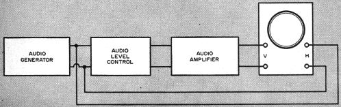
Fig. 3 - The number of loops measures frequency by comparison with a known standard.
"... the number is more important than the shape in frequency checking ..."
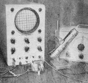
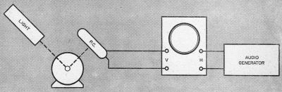
Fig. 4 - For measuring the speed of a small motor, a self-generating type photocell is mounted on the white insulator (top), catching flashlight reflection from revolving shaft. This signal is then compared by the 'scope to audio generator frequency. Block diagram below shows setup for this test.
Block diagram below shows setup for this test.
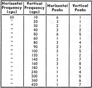
A few examples of calibrating audio frequencies (listed in "vertical" column) against the 60·cycle standard obtainable from the a.c. power line. An audio signal source is used to drive both the amplifier under test and the horizontal plates of the oscilloscope. The output of the amplifier under test is used to drive the vertical plates of the 'scope. If there is no phase lag present in the amplifier, the pattern will be a straight line as in Fig. 2(A) and will increase in length as the input to the amplifier is increased. When the overload point is reached, the pattern will take on the appearance of 2(B). At this point distortion increases rapidly. Figures 2(C) and 2(D) indicate that phase shift is present in the system. In many cases it will be found that the amount of phase shift varies with a change of signal frequency. Frequency Measurement Perhaps the most widely employed Lissajous patterns are those for frequency comparison. If separate signals of the same frequency are on the vertical and horizontal inputs to the 'scope, a circle or ellipse (depending on their phase relation) will be formed, as in Fig. 3(A). For each cycle, the spot will make one trip sideways and one trip up and down. For frequency comparison, a perfect shape is not important. If the frequency on the horizontal input is left unchanged and the frequency input to the vertical input is exactly doubled, the result will be a pattern like that in Fig. 3(B). In this case, the beam must make two trips up and down for each one across and back. If the frequency on the vertical deflection plates is made three times that on the horizontal plates, the pattern will be that of 3(C) because it must make three swings vertically for each one it travels horizontally.Reversing the situation and reducing the frequency of the signal on the vertical plate to one-half of that on horizontal will give the pattern of Fig. 3(D). The spot now has time to make two trips across while traveling vertically once. To get a usable pattern, the two frequencies being compared do not have to be exact multiples of one another. In Fig. 3(E), by counting the loops (or peaks), it is found that two horizontal excursions were made for each three that were made vertically. The frequency on the horizontal plates is then two-thirds of that on the vertical. Using this sort of frequency comparison, a home-built or commercial audio generator can be calibrated at a large number of points by using only the 60-cycle line current as a standard or one of the audio tones broadcast by the National Bureau of Standards on Station WWV. The table below shows a few of the cardinal points that can be calibrated by using 60 cycles as a standard. If the 600-cycle tone from WWV is used, all figures are multiplied by 10. This same method serves the "ham" in checking the multiplying stages in short-wave transmitters. A signal picked up from the input of the stage to be checked is compared with a signal taken from the output of the same stage. The number of loops in the pattern indicates the number of times the stage is multiplying the frequency. Almost all of the common makes of oscilloscopes will operate in this manner up to 30 megacycles if the signal is applied directly to the deflection plates. Mechanical Tests The value of an oscilloscope is not limited to those interested in sound or electronics. For the hobbyist who would like to know the speed of small motors, perhaps one too weak to drive a mechanical tachometer, the scheme in Fig. 4 (page 65) is the answer. The shaft has been given a light coat of dull black paint or ink and a white spot of paint is dabbed on one side. When a flashlight or some other source of light (operated on direct current) is directed on the shaft, the light reflected from the white dot as the shaft revolves induces a voltage in a photocell. This signal, which consists of one pulse for each revolution of the motor, is placed on one set of 'scope plates. If a signal from a calibrated signal source is placed on the other set of plates and adjusted until a single loop pattern is formed, the revolutions per second of the motor tested can be read from the oscillator. Almost any type of rotating machinery can be checked with this method by using the proper variation. The speed of a model airplane engine can be checked by shining the light through the rotating propeller to the photocell. Of course, the result must be divided by two, because the double blade of the propeller is generating two pulses for each revolution. Another variation of this same method is the use of a microphone to pick up sounds. The sustained note of a musical instrument can be picked up and the resulting impulses used to energize one set of 'scope plates. If the second set of deflection plates is fed from a calibrated audio signal source, the frequency of tone picked up by the microphone can be determined with precision. In using the Lissajous form of oscilloscope display, several things should be remembered. The general shape of the pattern is not important for frequency comparison. Ignore odd ripples and bumps. The number of line-crossings or loops is what counts.
Posted November 8, 2022 |
|