Liquid Crystals for Electronics
|
|
Liquid Crystals for Electronics
Imagine a 7-segment readout device that requires only 280 μW of power to operate and becomes more visible as the ambient light increases. Also imagine a cathode ray tube which appears normal in every respect, even to the image on the screen, except that the image has been stored there for more than a year with no electrical connection of any type and can be erased in milliseconds. Let your imagination run wild and conjure up fantasies of a panel light that costs only a penny, a flat-screen TV receiver, or a microwave fluoroscope. These devices either already exist or are anticipated to arrive on the scene in the near future. They are all possible as a result of liquid crystals. As their name implies, liquid crystal substances exhibit properties of both a solid and a liquid. Depending on their viscosities, liquid crystals can be poured like water, easily assuming the shape of their containers. However, due to selective reflection, white light striking a film of these crystals causes a different wavelength to be reflected at different angles of incidence, resulting in the iridescent colors typical of liquid crystals. Furthermore, since the crystalline structure which produces selective reflection is inherently weak, any force that causes this structure to shift or realign itself causes a different structure to be produced. This force can be thermal, acoustic, electrical, magnetic, or even mechanical.
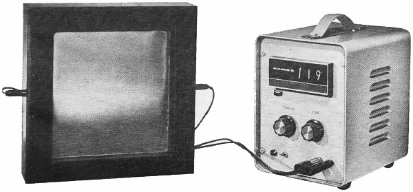
Fig. 1 - Liquid crystal microwave power density meter made by Bendix.
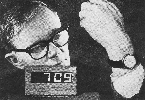
Fig. 2 - Prototype liquid crystal digital readout for watches and calculators. (Photo: RCA Labs.) Here, we will consider only thermotropic liquid crystals. These are compounds that exhibit a liquid/crystal phase, or "mesophase," at a temperature usually greater than the ambient. Thermotropic crystals can further be divided into three categories, two of which are of interest to us - cholesteric and nematic. Cholesteric Liquid Crystals Cholesteric liquid crystals, all derivatives of cholesterol, are the best known thermotropic compound. Currently, they are the most widely applied. The major property of these compounds is their ability to change color under the influence of different stimuli, notably temperature. When a layer of cholesteric crystals has been properly applied to a surface and illuminated by an incandescent light, the crystals change from colorless to red, yellow, green, then blue, and, finally, violet, as the temperature of the surface to which the crystals are applied passes through the mesophase range. Raising the temperature even more turns the crystals colorless. The process is reversible, with the same spectrum of colors appearing in reverse order as the crystals are cooled through the mesophase range. Since the colors scattered by cholesteric liquid crystals under incandescent light are unique to a given temperature, measurement of temperature is possible to an accuracy of better than 0.1 °C. Liquid crystals either mixed with a solvent or contained within 20-micron spheres (encapsulated liquid crystals), which are suspended in a water slurry, are available if you wish to apply them to surfaces like transistor heatsinks. To work with the solvent-suspended or encapsulated liquid crystals, a black background is a must. Some of the encapsulated types are sold in a blackened solution which leaves a black surface when dry. To use unblackened crystals, the surface to which they are to be applied must first be coated with a water-base black paint such as No. VL-447A available from Van-Light (9770 Conklin Rd., Cincinnati, OH 45452) at $1.00 for 50 cc. Edmund Scientific (300 Edscorp Bldg., Barrington, NJ 08007) stocks both the blackened and plain liquid crystals. The liquid crystal solution, a clear or slightly cloudy yellow solution, is designed to be air-brushed or aerosol-sprayed onto the painted surface, using a steady back-and-forth motion. An even coating about 1-mil thick will provide optimum results. Too thick a coating must be avoided. An excellent kit is offered by Liquid Crystal Industries (460 Brown Ave., Turtle Creek, PA 15145); it contains 12 bottles of pre-blackened liquid crystal solutions, a special aerosol applicator, and a Mylar hoop for indirect testing. Available in low and high temperature versions, the kits are each priced at $75.00. No color is visible until the spray coating dries and the surface being tested is at a temperature within the range of the liquid crystal being used. Dim colors mean the liquid crystal coating is too thin. If this is the case, put down another coat.
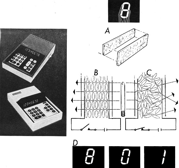
Microelectronic calculators such as those above with liquid crystal displays, are being manufactured in volume by such companies as North American Rockwell. In the display shown at (A), each digit has seven segments, each with an electrical lead, formed on glass plates with transparent tin oxide. Two glass plates are bonded together with about 1/1000 of an inch between them. This space is filled with liquid crystal material. Magnified drawing at (B) shows how material's molecules are normally uniform; but when subjected to electrical field (C), molecules are upset so that they scatter light rays and the area appears to glow. Different numbers are formed (D) by subjecting selected segments to electrical field, which causes those segments to glow brightly. Instead of applying the liquid crystals directly to a surface, it is much easier to work with them in encapsulated sheet form so that they do not become contaminated and can be used over and over again. Memory liquid crystal sheets have been developed; they turn black wherever the surface has exceeded the critical temperature. When the temperature decreases, the black area remains black, but simple brushing of the blackened area restores the original color. Experimental kits of all types of sheet material are available from Edmund Scientific in a small kit, Part No. 60,756, for $4.00 postpaid, or in a large kit, Part No. 71,143, for $10.00 postpaid. The property of cholesteric liquid crystals to exhibit different colors with changes in temperature has many direct applications in electronics. For example, the alignment of infrared laser beams is a difficult task by traditional methods. In comparison, either a sheet of liquid crystal materials or a sheet of metal with a layer of liquid crystal on its rear surface will yield a good image of the beam size and operating mode of the laser. The visualization of intensities in a microwave beam has also been easily accomplished by the use of cholesteric liquid crystals. A layer of liquid crystals is applied to a thin sheet of Mylar placed in a microwave beam so that energy transferred to the film heats up various segments in proportion to the amount of energy absorbed. Since the crystals indicate specific temperatures, distinct color lines form a two-dimensional plot of the microwave field intensity. An example of a device that uses this principle is shown in Fig. 1. In this instrument. built by Bendix Laboratories, the temperature range represented by the transition from red to blue is equivalent to a power spread of 7 dB. Nematic Liquid Crystals Nematic liquid crystals are currently causing a big stir in the electronics industry. Nematics are generally somewhat cloudy when viewed in bulk and tend to be a pale yellow in coloring. In small quantities or thin films, the haziness disappears. When placed under a microscope, the clear solution appears to have long wavy threads. If the liquid is probed or otherwise disturbed, the threads greatly multiply, slowly diminishing in number to the original quantity if no further disturbance takes place. These threads represent minute changes in the index of refraction between adjacent areas of the liquid. Under turbulent conditions, these area boundaries become many in number and tend to scatter light as the liquid turns an almost opaque white. To harness this turbulence, a cell can be fabricated to contain a solution of nematic crystals between two electrodes. When a potential is applied to the electrodes, a flow of ions is created which causes turbulence and turns the normally clear liquid crystal solution to a whitish color. This process is known as "dynamic scattering." The degree of whiteness and, correspondingly, the degree of reflected light, can easily be controlled by the voltage applied to the electrodes. Due to electrolysis depleting the liquid of ions, continued operation of the cell on dc will cause eventual failure of the nematic material. However, if an ac driving voltage is used, ion depletion will be greatly reduced. Like cholesteric crystals, nematic crystals have a mesophase that must be observed for proper operation. Until recently, nematic action was observed only in a narrow temperature band around 230° F. Continued research, however, particularly by RCA, is yielding nematic solutions usable over wider temperature ranges, including room temperatures. One of the most obvious uses for a material that reacts as nematics do is the currently popular 7-segment readout. An RCA prototype of a 7-segment readout is shown in Fig. 2. Since there is so little force required to create turbulence in a nematic, minimal power provides a good indication. Optel (P.O. Box 2215, Princeton, NJ 08540) was first to market a 7-segment liquid crystal readout device. Their No. 1003 display unit operates at 15-16 volts (ac for greater than 10,000 hours). The numerals form in 15-20 ms and decay in 100-200 ms. More important, only 40 μW of power is required per segment. Although the rise times are noticeable, they are acceptable in digital electronic clock, volt-meter, and airport arrival/departure sign applications.
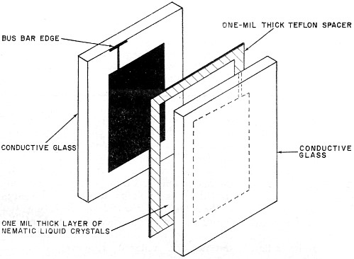
Fig. 3 - The diagram shows the physical arrangement of an experimental transmission-type nematic liquid crystal cell.
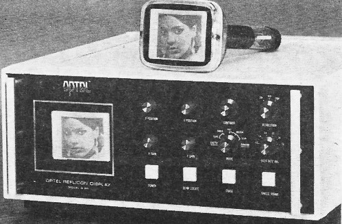
Fig. 4 - Nematic storage-mode Reflicon tube and demonstrator. (Photo: Optel) RCA has introduced a four-number 7-segment display and plans a matching COS/MOS IC for decoding and driving. Also projected are liquid crystal readout products from Display Tek of Dallas and from Texas Instruments. The Optel readout employs the reflective mode for imaging, making indication in a dark room impossible without a light source but affording excellent image clarity in areas of high-intensity ambient lighting. Displays employing the transmissive mode have been built in prototype by several companies, but these require a power-consuming lamp behind the panel. The uses for nematic crystals are not limited to readouts. Since the transmission of light can be controlled at will, it is possible to make automatically darkening windows, light shutters for optical systems, and many other similar devices. If the front and rear electrodes of a nematic cell are formed into a grid-like configuration in which the front sheet of glass has vertically oriented electrodes and the rear sheet has horizontal electrodes, only the nematic material at the crossover point of the electrodes, when energized, reacts by turning opaque. With addressing electronics, such a device is easily capable of displaying diagrams and images. Making a Nematic Cell For experimenters who wish to obtain first-hand knowledge of the nematic cell, materials are available for making their own. These consist of a pair of glass sheets, each coated on one side with a conductive material, a spacer, and the nematic liquid crystal material. These items will permit fabrication of a transmissive cell. If a reflective cell is desired, one of the sheets of glass is omitted and replaced by a sheet of darkened metal (such as black-anodized aluminum). Transparent conductive glass sheets can be obtained from several suppliers. Vari-Light, for example, has 2 1/8" X 2" X 1/8" sheets for $2.40 (No. CG-80 tin-oxide coated) and $1.50 (No. CG-75 gold coated) each. Larger sizes are available on special order. Although the gold coating has lower unit area resistance, the tin-oxide coating is slightly better since it transmits more light. When working with any type of conductive glass, the side with the conductive film should never be handled or otherwise contaminated. It should never be cleaned; to do so may damage the coating. Once you have the conductive glass, a spacer of the same length and width must be prepared from some nonreactive material such as 1-5-mil sheet Teflon. Cut a hole of the desired size out of the center of the spacer material. Next, place a sheet of the glass, conductive side up, on a level, flat surface and place over it the spacer. Now, using a thoroughly cleaned medicine drop-per, deposit some of the nematic solution on the sheet of glass within the confines of the cutout in the spacer. Make sure that the total amount of nematic solution deposited is no greater than the amount needed just to fill the hole and allow some room for expansion. Cover the assembly with the remaining sheet of glass. To finish assembling the cell, use a frame made from Plexiglas to hold it together. (Note: If you plan to cement together the cell parts, do not use an epoxy compound; it may react with the nematic liquid in the cell and ruin your efforts.) The procedure for assembling the cell is shown in the drawing in Fig. 3. To make a 7-segment readout assembly, it is necessary to remove only part of the conductive coating on one of the glass sheets, leaving "islands" of conductor to make up the segments and narrow bands to bring out to the bus bar along the edge of the glass sheet. The Van-Light conductive sheets have bus bars which can be cut into seven separate segments, each going to a separate segment of the display's conductive coating. To form the segments, a Dremel "Moto-Tool" with an abrasive rubber cone and a metal erasing shield can be used. The nematic solution for your cell can be obtained from Van-Light as Part No. VL-1047-N. It consists of a 5-gram bottle of liquid and sells for $12.80. The operating temperature range of the solution is 10°-47°C, which includes normal room temperature. Power requirements for your homemade nematic cell are minimal but will vary from cell to cell due to the assembly techniques used by different experimenters. If the nematic is from Liquid Crystal Industries ($15/gram, 5-gram minimum order), there will be typically about an 8-volt threshold, with 22 volts optimum. Resistivity is about 1010 ohms/sq cm, and the cell will yield a contrast ratio of at least 20:1. Although the cell will certainly operate on dc, the noticeable rise and decay times can be shortened by use of a 1000-Hz ac driving voltage. This experimental cell can be used as a light shutter, but the rise and decay times are still too lengthy to use it for modulating a laser beam with audio information. Storage-Mode Solutions By mixing a nematic crystal solution with a cholesteric solution (such as cholesteryl chloride), in a weight ratio of 9:1, a "storage-mode" liquid crystal solution is obtained. The solution is normally clear, but with 30 volts dc applied to it, it turns a milky white. Removing the voltage, the mixture regains its normal transparency only after several weeks. If desired, however, the material can be made transparent at any time simply by applying a 50-volt, 4000-Hz signal to the electrodes. With no power required to retain the image, the applications are virtually limitless. One application has already appeared in the Model D-10 Reflicon® tube produced by Optel and shown with its demonstrator/driver package in Fig. 4. As can clearly be seen, the image shown on the screen of the disconnected tube is stored without attached wiring. The particular tube shown held its image for more than a year with little degradation.
Posted September 7, 2020 |
|

 Inexpensive readout devices that get brighter
with more ambient light
Inexpensive readout devices that get brighter
with more ambient light