Leslie Effect Simulator
|
|
An RF Cafe visitor wrote to ask that I scan and post this article on the Leslie Effect Simulator, which appeared in a 1965 issue of Popular Electronics. "What the heck is the Leslie effect?" you are probably asking, as did I. Basically, it is a mechanism for artificially creating the "wobbulating" effect of a pipe organ in a large echoing environment. Inventor Donald Leslie worked for the Hammond organ company and developed an electromechanical contraption that rotated a baffle in front of speakers to create the effect. Commercial electronic Leslie Effect products were sold back in the 1960s and 1970s when high fidelity (hifi) stereo equipment was the "in" thing, like computers were in the 1990s and cellphones are now. There were a lot of electronics hobbyists that loved to build projects printed in magazines like Popular Electronics, especially since at the time many things could be built more cheaply than buying a finished product off the store shelf. Electric guitar players were big adopters of Leslie effect generators, and were used by lots of top musicians. You can buy some of the vintage devices - both mechanical and electronic - on eBay if you're interested. All-Electronic Organ Accessory That Sounds Like a Leslie
The true Leslie speaker system is a cumbersome and costly organ accessory. The almost identical sound effect can be achieved by inserting the device described here between the keyed tone generators and the power amplifier in your electronic organ. Through use of a wobbulated bandpass filter, the Leslie effect is reproduced by the main amplifier and speaker. Adjustments on the simulator permit the operator to duplicate roughly the acoustic effects of vibrato, tremolo, and Leslie. The special effects Leslie speaker system is a popular addition to any organ - acoustic or electronic. Usually a "Leslie" system refers to a mechanical means of obtaining a vibrato-like sound effect - a gentle undulation of intensity at a rate of 8 to 12 Hz. Even in modern electronic organs, the Leslie uses a massive rotating diffuser to disperse the sound from an extra speaker. It is effective, but also massive, noisy, and costly. Described here is a system which achieves nearly the same results with an adjustable all-electronic simulator. While cost and size are definite advantages, perhaps the best part of the electronic Leslie Effect Simulator is its versatility. With the controls cranked buck, the Simulator adds an interesting, subtle effect to conservative music. But if you're a wild man, you can really twiddle the knobs and wail! Control adjustments can produce anything from "super" bass or treble boost to sounds listeners describe us "shimmering, bubbly or out of sight!" Theory of Circuit Design. While the frequency shift, or vibrato, effect of a Leslie speaker system (see box) is expensive to generate electronically, the total effect can be convincingly simulated simply by placing a bandpass filter between the musical instrument and its amplifier and sweeping back and forth across the bandpass. This is the principle employed in the Leslie Effect Simulator circuit shown in Fig. 1. At the heart of the Simulator is an active bandpass filter composed of R14, R15, Q2, and C7 through C9 in the feedback loop of the amplifier/buffer combination made up of Q3 and Q4. Transistor Q1 and its associated components form a low-frequency phase-shift oscillator, the output frequency of which can be set from between about 4 Hz to 12 Hz through the use of speed control R4. The signal from Q1 is attenuated by weight control R8 and applied to the gate of Q2 to change the source-to-drain impedance of the FET and, consequently, the center frequency of the pass band. Photoelectric system I1/LDR1 is used to bypass the Simulator when the system is not in use. Closing a footswitch plugged into J3 powers I1 which, in turn, illuminates LDR1. Once illuminated, LDR1's internal resistance drops and forms a signal bypass loop around the filter circuit. Construction. Since only low frequencies are involved in the operation of the Leslie Effect Simulator, parts layout during assembly of the project is not critical. Just adhere to the general rules of neatness and good soldering. In particular, keep signal leads as short as possible.
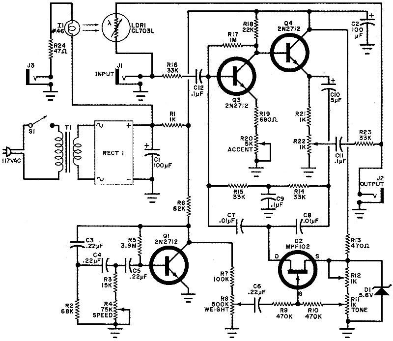
Leslie Effect Simulator schematic. Fig. 1. Footswitch plugs into J3; when closed, footswitch powers I1 which illuminates LDR1. With LDR1 illuminated, input signal at J1 goes directly to J2.
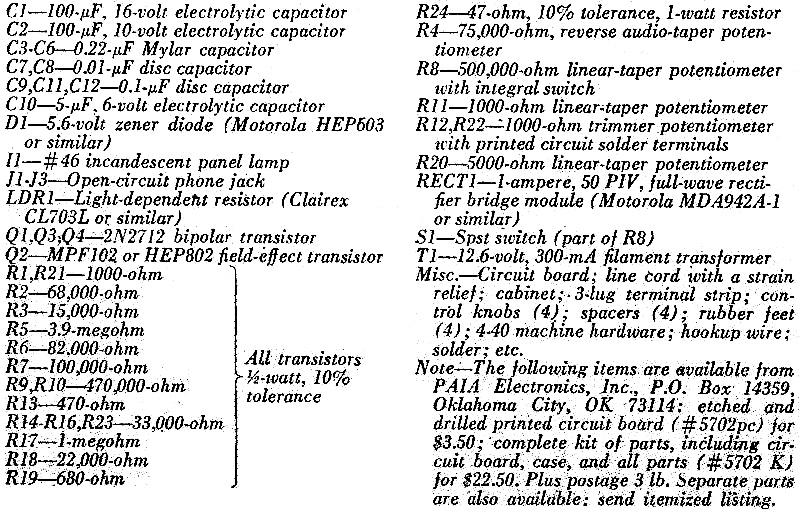
Leslie Effect Simulator parts list.
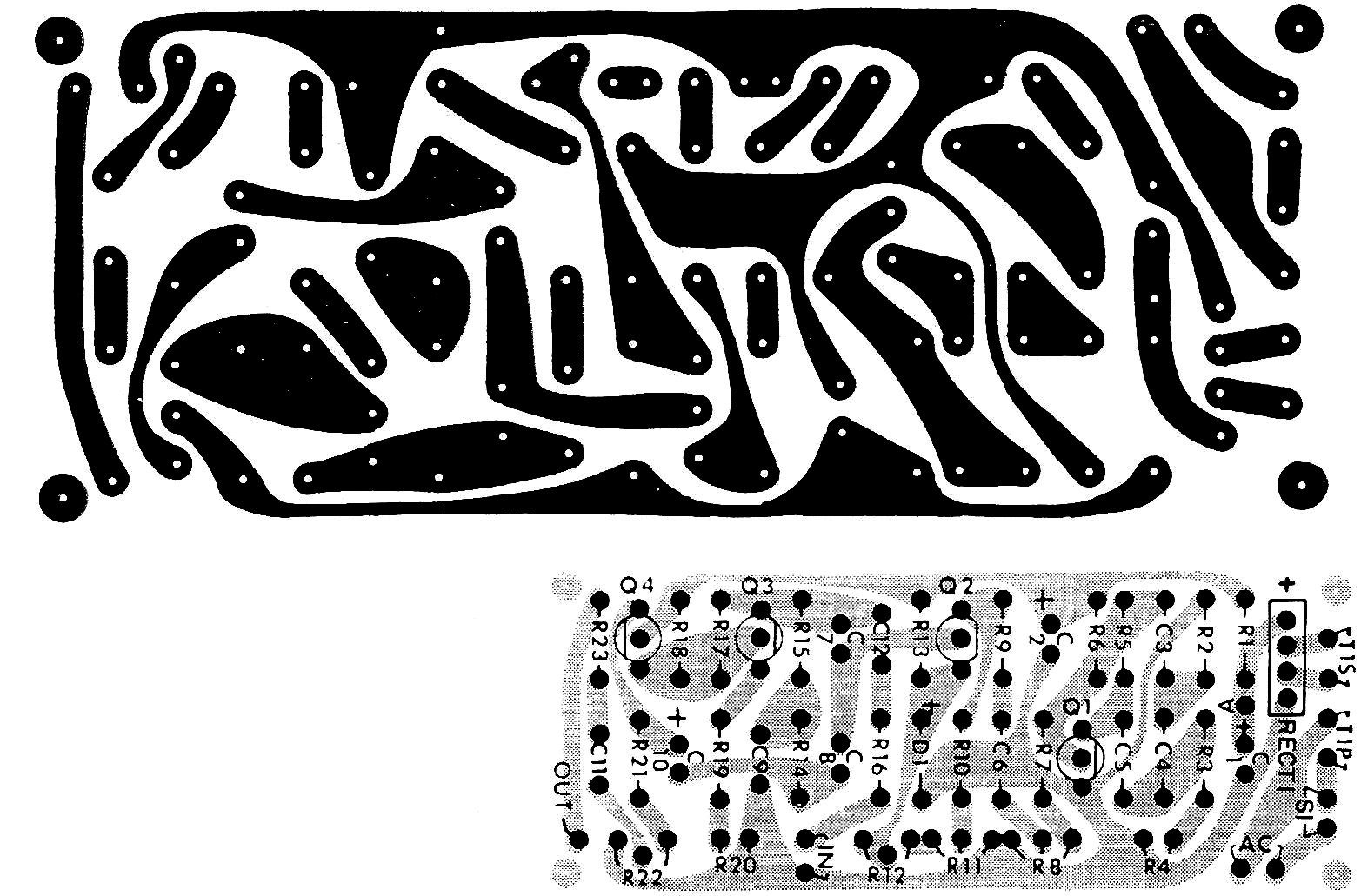
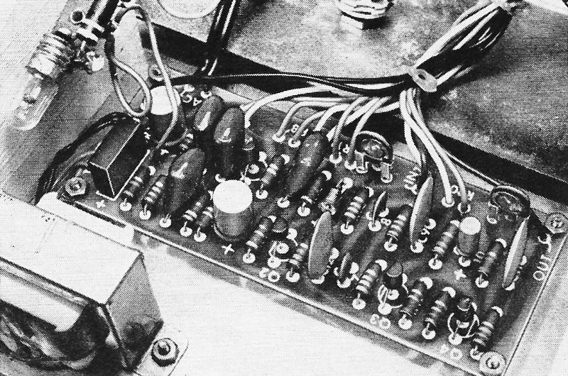
Fig. 2. Actual size printed circuit board etching and drilling guide is shown above. At right is components placement and orientation guide. Note orientations of flats on transistors and plus sign on rectifier assembly.
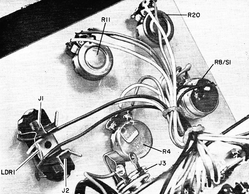
Input and output jacks J1 and J2 should be located close to each other if separate jacks are used to allow LDR1 to be mounted between them as shown here.
Neatly dress control and jack wiring to one side of circuit board and lace together with cable ties or lacing cord. Secure power transformer to chassis with 4-40 machine hardware; add 1/4" spacers when mounting board in place.
Current limiting resistor R24 and I1 are mounted on terminal strip fastened to side panel in line with LDR1 when cabinet is assembled. If side panel is metal, use four-lug terminal strip and do not connect R24 or I1 to mounting lug.
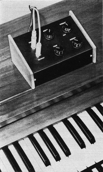
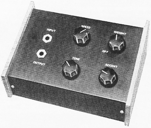
In prototype, top of case slopes downward. Top, front, and rear panels are painted flat black to contrast with rich tones of walnut side panels. Controls and jacks are lettered in white, using dry-transfer lettering kit. Begin assembly by etching and drilling the printed circuit board, carefully following the actual size etching guide provided in Fig. 2. (If you prefer, you can obtain a ready-to-use circuit board from the source listed in the Parts List.) Once the board is prepared, mount the parts in their respective locations, paying particular attention to the orientations of diodes, transistors, and electrolytic capacitors. Use a low-wattage soldering iron to solder the component leads to the circuit board's foil pattern. It is also a good idea to heat sink the leads of the solid-state component to prevent heat damage. After all components are mounted on the board, solder in place the primary and secondary leads of power transformer T1 and pieces of hookup wire sufficiently long to reach the front panel controls when the project is fully assembled. Then carefully check the foil side of the board, particularly around the transformer connections, for solder bridges. If any exist, reheat and remove any excess solder to eliminate the bridge. You can use just about any type of case that suits your fancy to house the circuit. If you wish to duplicate the case shown in the photos, all you need are some 22-gauge sheet aluminum, lumber, glue, and fasteners. No special tools are needed for forming and fabricating the metal parts. The top, front, and back of the case are made from a single sheet of aluminum, machined on the front and back panels to accommodate the controls, jacks, and entry for the line cord. It is then bent to shape to form a friction fit over the side panels. While you're at it, you can also cut to size the bottom plate, using the same sheet aluminum. To make the side panels, you will need one walnut and one white pine panel for each. Cut the walnut pieces 1/4" longer in their length and width dimensions than the height and depth dimensions of the metal pieces. The pine pieces should be 3/8" shorter in both dimensions than the length and width of the walnut pieces. Now, make a "sandwich" of the pine and walnut pieces with white glue and wire brads, centering the former on the latter. This done, smoothly sand and hand rub paste wax on the outer face and edges of the walnut panels to bring out a dull sheen. Then use short wood screws to fasten the bottom plate to both side panels and temporarily set the assembly aside. Next, paint the front, top, and back assembly with a color to contrast with the dark shade of the walnut panels. When the paint has thoroughly dried, use a dry-transfer lettering kit to label the controls and jacks. Mount the controls and jacks in their respective holes; then pass the free end of the line cord through its entry hole and secure it to the rear panel with a strain relief. Referring back to Fig. 1, connect and solder the free ends of the wires coming from the circuit board to the lugs of the appropriate control and jack lugs. Tin the free ends of the line cord and solder them to the hole locations marked AC on the board. Now, interconnect with lengths of hookup wire the ground leads of J1-J3 and connect and solder the leads of LDR1 directly to the signal lugs of J1 and J2. Neatly dress the leads along one edge of the circuit board. Now, mount R24 and I1 on a three-lug terminal strip (no lugs grounded). Position the assembly near LDR1 so that when the lamp is lit it will illuminate effectively the LDR. Mount the assembly in place with 4-40 machine hardware. Connect this assembly via one wire to the positive side of the power supply on the circuit board. Finally, mount the circuit board with 4-40 hardware and spacers, and power transformer T1 with 4-40 hardware only. The project is now ready to be tested. Setup and Use. Plug the line cord of the Leslie Effect Simulator into a 117-volt ac outlet. Connect an input and amplifier to J1 and J2, respectively, and a footswitch to J3. Turn on the system by rotating R8 clockwise just past the click. Close the footswitch to test the bypass circuit; I1 should immediately come on. Temporarily cover the sensitive face of LDR1 with a piece of black electrical tape to keep ambient light from interfering with the adjustments to be made. Advance Accent control R-20 to about two-thirds of its clockwise rotation and set weight control R8 fully counterclockwise - but do not click the power off. The maximum effect of Tone control R11 occurs over about one-quarter of its travel. The extra travel is useful in some effects when the weight control is fully advanced. Adjust R12 so that the most sensitive area of the Tone control is at the center of the Tone control's travel. You can check out your settings by striking a chord and noting the action of the Tone control as it is rotated. Trimmer potentiometer R22 should be swept over its entire range to check the gain of the Simulator. It should then be set so that there is minimum change in volume level as the Simulator is switched in and out of the system (by operating the footswitch). While adjusting R22, be sure to remove the tape from over the LDR to permit switching out the Simulator. To a certain extent, Accent control R20 changes the overall gain of the Simulator. It should be adjusted for unity gain at the accent setting you intend to use most often or for whatever compromise suits your taste. When both internal adjustments (R12 and R22) have been made, uncover LDR1 and assemble the case. In use, the best way to get the feel of the controls of the Simulator is simply to play with them. However, a few simple hints will get your started. First, to obtain the Leslie Effect, set the Accent control to approximately the center of its travel and rotate the Weight control a small fraction of a turn clockwise. Set the Tone control to the center of its travel and adjust the Speed control as desired. Now, when the instrument plugged into J1 is played, you should get an effect that is something like a tremolo, except that there will be a touch of sweeping pass band in the background. If the effect is not pronounced enough to suit you, advance the Accent control. For super bass/treble boost, turn up the Weight control as far as it will go without turning off the Simulator. Advance the Accent control all the way. Now the Tone control can be rotated clockwise for treble boost and counterclockwise for bass boost. Somewhere between the two extremes, the amplifier might break into oscillations, but this can be readily remedied simply by backing off on the Accent control slightly. Advancing the Weight control past its midpoint and setting the Tone slightly treble of center can produce an effect quite similar to reverberation if the Accent control is advanced to the point that just causes oscillation when a note is struck. If, during the operation of the Simulator, you notice a loud ac hum level, try reversing the ac line cord plug. This should effectively curb the hum loop. Beyond the very rough hints outlined above, familiarizing yourself with the Leslie Effect Simulator will depend on your experimental nature. You will certainly want to experiment to determine just what the Simulator is capable of doing. Go to it. The "Leslie Effect" In principle, the Leslie speaker system is nothing more than one or more loudspeakers mounted at the end of an arm which is rotated by means of a motor. (Other variations use a fixed speaker and employ a rotating "paddle" or baffle, but the principle is the same.) As the loudspeakers swing around in an arc, several things happen to the sound. First, a Doppler shift in the apparent pitch of the sound is caused as the motion toward and away from the listener takes place. Next, a variation in sound level is produced as the speaker alternately faces toward and away from the listener, Finally, there occurs a great variety of effects which stem from changes in the acoustics of the system enclosure and the room in which the system is being used occur.
Posted April 25, 2024 |
|