The "Scrounge" - an Instant "J" Antenna
|
|
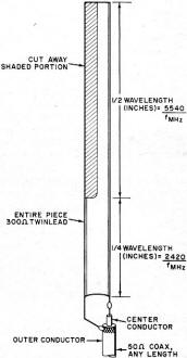
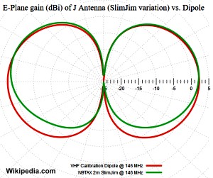
J-pole antennas (aka "J" antennas) are so named due to their physical shape (see drawing below). The basic "J" antenna is a half-wave vertically polarized antenna that has an integrated parallel feed quarter-wave tuning stub. It is very popular with amateur radio operators and is still used with some commercial radio installations. The azimuth radiation pattern and gain are very similar to the half-wave dipole antenna, as shown in the Wikipedia plot below. The J-pole was invented in 1909 for use on the German Zeppelin airships as a trailing wire antenna. Variations of the J-pole have evolved over the years that in some cases significantly change the radiation pattern, but the characteristic quarter-wave stub match is retained in all of them (see the Wikipedia page). The "Scrounge" - an Instant "J" Antenna You Can Whip a VHF Antenna Together in 30 Minutes By Albert S. Von Trott, W3UIX/6 The "J" style antenna has been around for years and years. Hams, police, forestry and fire radio stations started using the "J" back in the 1930's, and even today it is not uncommon to see a Business Radio system using "J" antennas. The advantages of the "J" are the omnidirectional characteristic of the radiated pattern and the vertical polarization - two important requirements in working mobile and vertically polarized stations. The short wavelengths of the very high frequencies also favor the use of these vertical antennas.
You can build a "J" antenna from a short length of 300-ohm twin lead a la "Sneaky Pete" in just about 30 minutes. A very desirable feature of the "J" antenna is the built-in quarter-wave match-ing section which lets you use a regular 52-ohm coax transmission line; VSWR's of less than 1.3:1 are not unusual. The drawing shows the simple layout of the "Scrounge" with notations for determining its length. If you are working a band of frequencies, cut the antenna to resonate in the center of the band. If you are interested in listening on 156 MHz, for example, simply divide the figure 5540 by 156 to determine the length of the half-wave section (35 1/2"). This is the radiating portion of the "J." Add to this dimension the length of the quarter-wave matching section (2420/156 = 15.5) to find the total length (approx. 51"). The higher the frequency, the shorter the antenna. The rest is simple. Cut one conductor 35 1/2" from the end of a 51" piece of 300-ohm twin lead and remove it. You can use a knife to cut the insulation, or you can strip out the undesired lead by getting a good grip on the cut end and pulling. Don't try it with your fingers or your teeth; use a pair of diagonals or pliers. Tape your "Scrounge" to a wooden pole, solder the wires at the bottom of the "J" to your coax feed line, and you're in business. You could hang this antenna from a tree, or - if you want to get fancy-substitute aluminum or copper tubing, but maintain the same dimensions. If you support the lower part of the antenna with insulated standoffs, you'll have a first-class permanent installation. If you hang the antenna from a tree or other high structure, you can reverse the connections to the coaxial cable to provide for some degree of lightning protection. With the leads reversed, the highest point of the antenna will be connected to the coaxial cable's shield, which is usually grounded at or near the equipment. Antenna action is not materially affected by this reversal because the quarter-wave section acts like a transformer. As with any antenna work, there is no substitute for actual on-the-job tuning, adjusting, and other optimizing activities. The figures shown are close enough for most applications, and include some consideration for end effect. If you want to experiment using a cut-and-try technique, you can first try shortening the quarter-wave section about 1/2" at a time before modifying the half-wave section. Telescoping sections such as are found on a pair of TV "rabbit ears" could help you pin down the exact dimensions.
Posted May 28, 2018 |
|


