The How and Why of the SCR
|
|
Did you know that General Electric introduced the first silicon-controlled rectifier (SCR) for commercial use? It was in 1957 when this article appeared in Popular Electronics magazine. The SCR was one of the first really high power devices in the semiconductor industry, not for its voltage and power gain, but for its ability to switch very large currents on and off while having a relatively low "on" voltage drop. This article gets into the basic theory, operation, and application of the SCR. The S-band airport surveillance radar that I worked on in the USAF originally used a vacuum tube thyratron to trigger the magnetron's pulse forming network, but that tube was replaced with a solid state SCR circuit that plugged directly into the original thyratron tube socket. The How and Why of the SCR
Cutaway view above of an SCR courtesy of International Rectifier Corporation. Principles of Operation and Applications of the Silicon Controlled Rectifier By Joseph H. Wujek When the semiconductor industry began to expand in the 1950's, transistors and solid-state diodes and rectifiers quickly replaced their vacuum-tube counterparts in many applications. Then as now, the complete transition from tubes to semiconductors was not possible because of the limitations of the latter. In 1957, however, an important step toward the goal of total replacement by semiconductors was taken when General Electric Co. introduced the silicon controlled rectifier, or SCR. Briefly, the thyratron permits the control of power in switching applications with only a small energy loss in the control circuit. By applying a signal to a control grid, the thyratron is made to conduct between a pair of electrodes (anode and cathode) and remains conducting with no further excitation at the control grid. In fact, in normal operation, the grid ceases to control the thyratron once conduction begins. To stop conduction, the anode must go from a high positive potential to near zero as in the phase reversal of a 60-Hz power line.
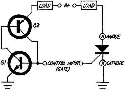
Fig. 1 - The transistor circuit at left is equivalent to actual SCR at right. The SCR performs in an analogous manner; and, in addition to the inherent improvements in reliability and simplicity afforded by semiconductors, some of the kindred devices of the SCR can function as turn-on/off systems to control bidirectional currents, an impossible task for the thyratron and other vacuum tubes. How It Works. The operation of the SCR is perhaps best understood by examining the device's pnpn junction, shown in equivalent form by the two transistors in Fig. 1. Assume that the control (gate) electrode is connected so that its voltage is the same as, or slightly negative with respect to, the voltage on the cathode. Transistor Q2 is cut off and only leakage current flows in the circuit. If the gate voltage is made positive with respect to ground, the base-emitter junction of Q2 becomes forward biased and Q2 begins to conduct. Moreover, Q1 also becomes forward biased and conducts. As Q1 starts conducting, its collector current aids in turning on Q2, just as collector current from Q2 assists in turning on Q1. This mutual aid is a form of regeneration, or positive feedback. A point is reached at which the switching action "runs away" from the control input and becomes self-sustaining. In regeneration, Q1 and Q2 are operated at saturation, and the voltage drop from the collector of Q2 to ground is the sum of the 0.7-volt base-emitter drop of Q1 and the 0.2-volt collector-emitter drop of Q2. (The voltages are for silicon transistors only.) Thus, the switch exhibits a low voltage drop and requires no control input power to sustain conduction. To turn off the circuit, the current in the transistor bases must be internally reduced to a level at which the current gain of Q1 and Q2 is insufficient to supply the required currents. Since it is not practical to get into the transistor junctions, the current in the emitter-collector branch is reduced. This is accomplished automatically if the supply voltage is derived from an ac source. (The SCR is primarily an ac device, although in dc applications it will serve as a "latch," or memory switch, and remain conducting until the anode current is reduced or interrupted.) The point at which the anode current of an SCR is sufficient to keep the device conducting is called the holding current. The peak voltage (anode positive with respect to cathode) at which the SCR does not undergo breakdown for given conditions of bias between the gate and cathode is the the peak forward blocking voltage; this is usually specified with the gate connected to the cathode through a low resistance. The peak reverse voltage with the anode negative with respect to the cathode is also specified with the gate connected to the cathode through a low resistance.
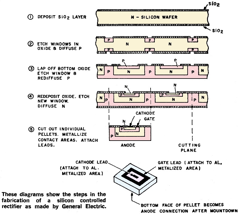
These diagrams show the steps in the fabrication of a silicon controlled rectifier as made by General Electric. Leakage currents increase with temperature increases and roughly double for every 10° C rise. In Fig. 1, the transistors cannot distinguish between currents caused by leakage or from a triggering pulse. Hence, care must be exercised in determining the temperature environment and external circuit conditions to prevent thermal turn-on. Other unwanted turn-on mechanisms are the device's built-in junction capacitances which provide paths for current when the anode-cathode voltage is changing. Current through a capacitor is proportional to the voltage rate of change with time. A fast changing voltage can introduce sufficient current to trigger the SCR. This parameter is specified as the "critical time rise" and usually is given in V/μS. The forward and reverse breakdown volt-ages have already been mentioned. Unless some means of externally limiting the current is used, these breakdown voltages will destroy an SCR. Except where severe transient voltages are present, the breakdown voltages will present no problems if the specified ratings are not exceeded. Parameters & Characteristics. If the SCR is to be intelligently employed, it is essential that the user be familiar with the device's various parameters and characteristics. These specifications are given in the manufacturer's data sheets. In choosing an SCR, first check the maximum allowable ratings, including the maximum current handling capacity which may be stated as average current or rms current or both. To use either specification, the current waveform through the SCR must be known. The peak surge current, usually specified for a 60-Hz half-wave excursion, is the current the SCR can handle on a low duty-cycle basis, permitting the SCR to cool off between surges. These currents can be as much as 10 times greater than the rms current. Such ratings are useful when the SCR is employed in "crowbar" operation to discharge a capacitor bank. Power ratings for the entire SCR, as well as for the gate circuit are often stated. These ratings depend on ambient and case temperatures. Maximum voltage and current in the gate circuit are sometimes specified. Finally, temperature limits for storage and operation are given. The low-temperature limit is dictated primarily by the differences in thermal expansion between the chip and surrounding materials. The upper limit is set by considerations of damage to the crystal substrate.
Typical SCR packages for International Rectifier Corp. units which have current ratings from 50 to 100 amps. When using the SCR as part of a circuit, the peak reverse and peak forward blocking figures specified are the currents that flow at given sets of bias conditions when the SCR is not conducting. These currents can be viewed as leakage and must be stated for a given temperature or temperature range. An SCRs leakage is on the order of 0.1 percent of its forward current. Hence, an SCR rated at 100 amperes forward current cannot be used to control a 50-mA load since the leakage current will be about the same as the current being controlled. The gate trigger voltage and current are specified for given anode-to-cathode voltages and gate-to-cathode resistances. They are temperature-dependent and often graphically plotted for SCR's not to trigger. The minimum values for firing at given temperatures also appear on the plots. This information specifies the voltage and current required for triggering the SCR, as well as the bias conditions to be maintained in the blocking state. The peak on voltage is the drop between the anode and cathode for a given load current and temperature. It is generally in the range of 1 to 2 volts. The holding current specifies the level to maintain to prevent the SCR from turning off. The turn-on and turn-off times are stated for SCR's intended for high-speed switching. The operating conditions must be specified if these parameters are to be useful. Some fast SCR's have low-current switching times in tens of nanoseconds. Design Considerations. Once the SCR is inserted between the power source and the load, a means must he provided for triggering it. When used to control ac, one of the simplest ways of triggering is to use the phase control method. The negative alternation takes care of the turn-off. Then all that is necessary to drive the SCR into conduction is application of a pulse to the gate when the anode is positive with respect to the cathode. A phase control triggering scheme in its simplest form is shown in Fig. 2. By choosing the appropriate resistance and capacitance values for the network, the time, or phase, relationship of the gate with respect to the anode-to-cathode voltage can be determined. Household lamp dimmers often are designed this way and may employ two SCR's back-to-back to control both ac alternations. Because the phase between the gate and anode-to-cathode voltages determines the time the SCR conducts, the average current through the SCR is dependent upon this relationship. The firing angle can also be derived from an isolated source like an error signal in a feedback system. When more current is needed, the error signal "tells" the trigger circuit to advance the gate voltage to turn on the SCR earlier in the cycle. This results in an increase in average current flow since the SCR conducts for a longer period of time.
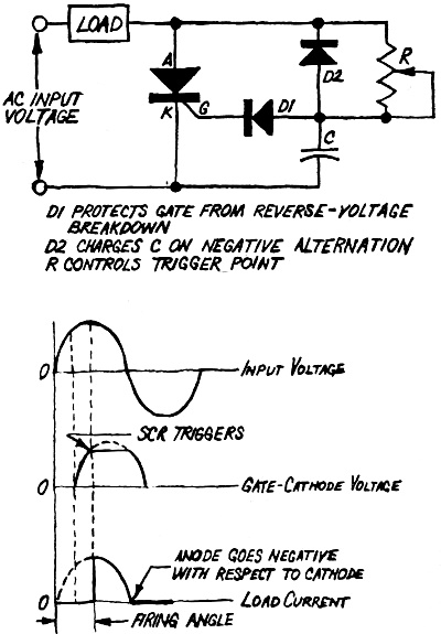
Fig. 2 - Schematic of a typical pulse triggering circuit to turn on SCR. Waveforms below show voltages and current and indicate the firing angle. A transformer provides good isolation between the trigger circuit and the load. The control signal might be a dc voltage, such as the on/off conditions of a switch or logic circuit. A simple oscillator can be used to furnish the gate pulses, controlled by a simple AND gate. If moderate or high currents are to be controlled, the fast turn-on of the SCR can generate high-frequency noise that will be radiated into space and passed along ac power lines. These noise spikes may interfere with radio and TV reception and cause malfunctions in interference-sensitive equipment. Filters can be used in the power line to reduce this noise, but a different means exists for drastically reducing or eliminating the noise. If the time at which the anode voltage crosses through zero and begins its swing toward positive (with respect to the cathode) can be sensed, a trigger pulse can be provided at that instant. The SCR then starts conducting early in the positive alternation and the current (in a resistive load) follows the sine wave of voltage rather than suddenly jumping from leakage level to a high forward level (see Fig. 2). Several manufacturers offer IC's designed specifically as zero-voltage detectors to use in this application. Applications. Apart from the familiar lamp dimmer switch and speed controls for certain types of ac motors, the SCR is used in the home to provide continuous (as opposed to stepped) control of heat in electric kitchen ranges. In industry, the SCR is used to control power in battery chargers, power supplies, and machine tools. Welders, power regulators, and temperature control systems have been designed using the SCR as a power control element. Among the most popular of automotive electronic ignition systems available is the SCR-fired system and its variations. And new applications for the SCR are continuously being discovered.
Posted February 13, 2024 |
|