Finding Your Way in Space
|
|
Just as today's generation of engineering students grew up with and are totally accustomed to and proficient at using computers, smartphones, positioning devices, CAE software, and various combinations of the aforementioned, so have the latest cadre of pilots grown up with GPS and electronic flight charts and planners in the cockpit. The difference is that whereas engineering students are not still required to learn to use a slide rule and a drafting table to earn an engineering degree, pilots are still required to learn to navigate using primitive (not meant derisively) instruments and ground-based navaids to earn a pilot's license. That's not a bad thing, though, because whereas if your graphing, 2500-function calculator quits working, the only thing at risk is your test score if you happen to be taking an exam. However, if your electronic navigation fails while in a limited visibility environment or in controlled airspace, you had better be able to do some seat-of-the-pants flying or you could be in deep doo-doo. This 1958 article from Popular Electronics magazine presents the newfangled TACAN (TACtical Air Navigation) and Loran (LOng RAnge Navigation) systems recently introduced (at the time) by the CAA (Civil Aeronautics Authority), which is now the FAA (Federal Aeronautics Administration). It was to dead reckoning navigation what the HP-35 calculator was to the slide rule. Finding Your Way in Space
It's a long haul from the old sea dog to today's jet There was a time when a well-moistened forefinger was a man's only navigation instrument. The cool side told him the wind direction-and thus, his course. Today, man relies on the thin metal "forefingers" jutting from high-speed high-altitude aircraft to keep him informed on position, direction, velocity and other data so necessary to flight. And satellites circle some 300 to 400 miles above the earth - spring-loaded "forefingers" busily transmitting spatial information back to us. The evolution of navigation from an uncertain art to a specialized science has been long and arduous. Its basic principles have always existed - they only awaited discovery. By necessity, navigation has always tagged along in the wake of mathematical and astronomical development. The ancient Greeks, we know, taught that the world was round and that any position on its surface could be determined by latitude and longitude. Basic principles, therefore, did not mystify man so much as the instruments used to verify them. Direction by Radio
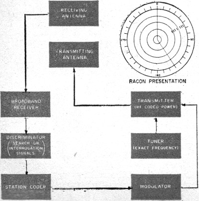
Block diagram shows what's behind the "beam" that pilots fly on the CAA network of airways. The development of electronic aids to navigation begins within our present century - in the early 1900's when Marconi's wireless made radio direction-finding the first electronic aid. Early shipboard direction finders were simple loop antennas, with a tunable receiver (100 to 1800 kc.), a set of earphones, and an azimuth indicator. To operate, the navigator simply tuned in a radio station of known position, rotated the loop to minimum gain, and then read the relative bearing on the azimuth indicator. By using several such stations - the more the better - and drawing the bearings on a chart, the ship's position was located at the intersection of the bearings. As refinements were made on radio direction-finding equipment, the speed and range of aircraft were steadily increased. Aerial navigation amplified existing problems of navigation, and introduced many new ones. For instance, the time allowed to compute position decreased in direct proportion to the increasing flight speed. A part of this new problem was solved by the low-frequency radio range. Now standard for nearly all airplanes, radio range equipment makes use of a network of ground stations and a receiver in the airplane. In operation, four radio beams of approximately 3° width are transmitted along the CAA (Civil Aeronautics Authority) airways - intercontinental "super-highways" 10 miles wide which are divided into 1000' altitude levels. Basically, the ground station has two pairs of transmitting antennas, each matched pair being placed at diagonal corners of a square. One pair transmits "A" (dit dah), the other pair "N" (dah dit) , The signals are transmitted in a figure-eight pattern. A and N signals overlap to provide equal signal intensity along the four 3° beams. The pilot tunes his receiver to the proper station frequency, between 200 and 400 kc., and listens for the station's call letters, e.g., LGA for La Guardia Field, New York. Once identified, the pilot hears either A or N in keyed intervals. (The N signal is always assigned to the quadrant containing true North to minimize confusion.) If the pilot hears an N, he knows he is off the beam, and he turns left or right. In so doing, he notes that the original N grows into a steady tone where the dah dit and dit dah overlap. When the pilot cannot distinguish A or N, he is "on the beam." Radar and Racon
Simplified diagram below shows how the Racon (RAdar beaCON) operates. Note use of scope.
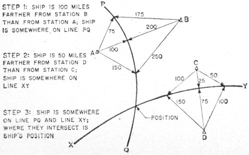
Plotting a ship's position by Loran makes use of the intersection of two hyperbolas, which are obtained by tuning in two pairs of stations. The big impetus to electronic aids came during World War II, with the advent of radar. Using narrow beams of microwaves of 1 to 12 cm. in wavelength, radar measures the time it takes an energy pulse to travel out, echo off an obstruction and return. One mechanization of this effect is Racon (RAdar beaCON), which provides the air navigator with both distance and bearing information on a standard PPI (Plan Position Indicator) scope. Airborne Racon equipment includes a primary radar operating on a frequency in the 200- to 10,000-mc. frequency range. The ground beacon consists of a secondary radar containing a receiver, time-delay unit and transmitter. In operation, the navigator "interrogates" the ground beacon with a pulse from his radar. This triggers a coded pulse from the beacon which is transmitted in all directions. The navigator observes the beacon response on a PPI scope in much the same manner as he observes targets. To differentiate between Racon signals and target echoes, the beacon signals are coded as a series of pips as detected by the PPI scope. Thus, bearings to the beacon can be taken, and distance measured. Effective range of Racon operation is limited only by the horizon or line-of-sight distance. A more specialized system is DME (Distance Measuring Equipment), though bearings to the ground beacon are not given. Fundamentally, the ground equipment for DME is like that used for Racon. The airborne equipment, however, differs in that the distance is shown on a dial indicator instead of a PPI scope. Because this indicator is susceptible to beacon interrogation pulses by other aircraft, the airborne equipment contains a sweep-search circuit in addition to a tracking circuit. In operation, the airborne transmitter sends out a 936- to 986-mc. beam. A separate receiver antenna picks up the beacon and any other transmissions. Airborne VOR. Should the navigator wish to determine course direction and not distance, he can use one of several omnirange systems: low-frequency, v.h.f. or u.h.f. The omnirange equipment provides the navigator with accurate courses either off or on the airways. With the VOR system (V.h.f. Omnidirectional Range), the navigator or pilot selects a station from a chart published by the CAA. He next tunes in the frequency of the selected station by means of a dial, and checks the coded or voice call of the station with that given on the chart. The magnetic bearing of the station from the aircraft is set into the system by means of a selector wheel; the bearing of the station is thereafter retained at all times until changed to a new station. Two other very essential parts of the airborne VOR system are the "left-right" and the "to-from" indicators. Once the magnetic bearing of the station has been selected, the pilot-navigator checks the "to-from" indicator to determine if his aircraft is flying toward or away from that station. The "right-left" indicator then guides him to the station by means of "flying to the needle." If the needle points to the left of the correct course, the pilot should turn left until it centers once more; if it points to the right, he turns in that direction. Loran. Another major electronic aid to navigation emerging from World War II was Loran (LOng RAnge Navigation). Though primarily associated with sea rovers, Loran is also used successfully for aerial navigation. It is the only method that does not rely on dead reckoning to compute position but rather on the hyperbolic functions of analytic geometry. Assume that we are standing some distance from two mountains. We find that mountain A is 100 miles from us, and B is 150 miles away. The difference in distance is 50 miles. Now we can move so that the difference in distances always remains 50 miles, but only if we move in a hyperbolic path. This is the basic method used in Loran, the major addition being that there must be at least two pairs of "mountains." By using two pairs, two hyperbolas result, and the point at which they intersect is the ship's position.
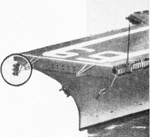
Tacan, shown atop the mast of the new supercarrier "U.S.S. Forrestal," and u.h.f. radio by Federal Telecommunication Labs (left circle) play important role in America's air-sea defense.
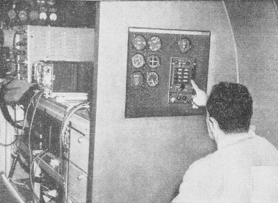
Flying laboratory of Federal Telecommunication Labs flight-tests Tacan under all conditions. In standard Loran, a pair of ground transmitters sends out pulses at the rate of either 25 or 33 1/3 per second. Antenna output is about 100 kw. at frequencies between 1700 and 2000 kc. Another nearby pair of stations, on the same frequency, provides the navigator with the second hyperbola. Aboard ship, the navigator has a conventional superheterodyne receiver with four broad channels which are fixed-tuned. The navigator selects any pair of stations, tunes in and reads the time difference between the two signals on a cathode-ray tube. He selects at least one other pair and repeats his computations. The intersection of the two hyperbolas is then found on a specially gridded Loran chart. A good navigator can obtain a fix in less than five minutes. Range of Loran navigation varies from 700 miles during the day to twice that at night; reflection of waves from the ionospheric layer in the evening gives this range boost. Ground waves, of course, are primarily used because of their accuracy, though tables have been prepared to take into account any sky wave reflections during nighttime operation. Tacan
Illustration of how the Tacan system works. Last and latest on the list of electronic aids to navigation is all-weather Tacan (TACtical Air Navigation). Tacan operates in the 1000-mc. band with 126 clear-frequency, two-way channels available, each channel being spaced 1 mc, apart. In the 1025- to 1150-mc. band, 126 frequencies are available for air-to-ground transmission; for ground-to-air transmission, 63 frequencies are available within the 962- to 1024-mc. band, and 63 more are in the 1151- to 1212-mc. band. In operation, the plane transmitter sends a distance interrogation. This pulse is retransmitted by the beacon, and electronic measurement of the elapsed time interval is converted to distance in miles. Azimuth bearings are determined by measuring the phase difference of a periodic transmission of a main and auxiliary reference burst from the beacon. Identification of the station is made by keyed Morse characters at regular intervals. We've come a long way in advancing the science of navigation to a safe, dependable means of traveling from here to there. There's always the chance that a tube can blow, or an amplifier can malfunction, and throw the whole system out. But we'll have to admit that it beats holding up a wet forefinger to the wind.
Posted August 2, 2022 |
|
 By Brooks Currey, Jr.