The Field-Effect Transistor
|
|
Although the first patent for a field effect transistors (FET) was assigned to Julius Edgar Lilienfeld in 1925, it was not until sometime around 1960 that the first commercial product was available - a MOSFET designed by Dawon Kahng and Martin M. (John) Atalla at Bell Labs. This article from a 1972 issue of Popular Electronics magazine introduces the hobbyist readers to properties and uses for the by-then common junction FET (JFET) and MOSFET. Nowadays, MOSFETs are the backbone of the vast majority of integrated circuits. Note in Fig. 3 where it is shown how the biasing and function of a vacuum tube and n−type JFET are essentially the same. I often recommend to people who are doing one of the Popular Electronics Quizzes that shows a vacuum tube that they mentally substitute a FET for the tube, and proceed to arrive at an answer. The Field-Effect Transistor: What It Is and How It Has Revolutionized ElectronicsBy William R. Shippee Ever since its introduction, the field-effect transistor has been creating quite a stir in electronics. Devices and systems heretofore impossible to produce with bipolar transistors had to be built around vacuum tubes - if at all. Now, the FET is changing the situation.
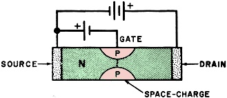
Fig. 1 - FET acts as variable resistor in which the gate field has a direct effect on source-to-drain current flow.
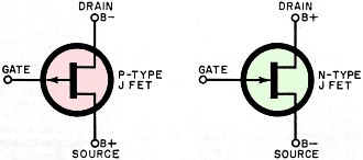
Fig. 2 - Shown here are the schematic symbols for a p-type (left) and an n-type junction field-effect transistor.
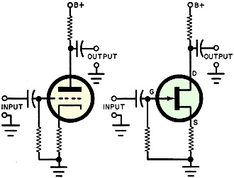
Fig. 3 - Biasing arrangements for n-type JFET and vacuum tube triode are same.
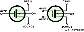
Fig. 4 - Schematic symbols for single-gate and dual-gate MOSFET's are shown here. The FET has many of the qualities and advantages of both the vacuum tube triode and the bipolar transistor. It is as compact as most small-signal transistors. It operates at low voltages, thus eliminating most of the bulk and expense of the power supply. Its input impedance can be rigged to fall into the desirable multi-megohm category. Recent developments have produced FET's which are capable of dissipating several watts of power; and since they exhibit the property of having a negative temperature coefficient, it is hard to make them succumb to thermal runaway. Viewed as a design element, the FET is a semiconductor device which behaves in the manner of a variable resistor. As shown in Fig. 1, current flow between the source and drain is controlled by the gate voltage which is applied to both p sections simultaneously. As the reverse bias increases, the space charge area starts to pinch off, causing the source-to-drain current to fall almost to zero. Thus, the gate "field" has a direct "effect" on the source-to-drain current - hence the term "field-effect" transistor. Types of FET's. There are basically two types of field-effect transistors in regular use today. The most common is the junction field-effect transistor, or JFET, which has a direct ohmic contact at the gate. The MOSFET, or metal-oxide field-effect transistor (sometimes known as an IGFET for insulated-gate field-effect transistor) has an electrically isolated gate. In the JFET category, there are p- and n-channel types (see Fig. 2). The n-channel FET is very similar in voltage polarities and biasing to the vacuum tube triode as shown in Fig. 3. The MOSFET, a long-needed semiconductor device, even more closely approximates the input impedance of the typical vacuum tube. It can be fabricated to yield gate impedances well into the several hundred megohm region - beyond the usual capabilities of the common JFET. As shown in Fig. 4, there are currently two types of MOSFET's available. The one on the left is a single-gate type, while the one on the right has two gates. The MOSFET's substrate is usually connected internally to the source; if not, the substrate is externally connected to the source or to ground. Great care must be exercised in handling the MOSFET since the gate input impedance is so high and the gate insulation is so thin that any static charge introduced at the gate can perforate the oxide insulator barrier and destroy the device. The dual-gate MOSFET finds its most popular application as the mixer stage in AM, FM, and TV tuners where it provides a convenient means of "beating" two frequencies in a nonlinear device while maintaining isolation between the two signals. Also the MOSFET appears to exhibit less noise and cross modulation problems than do conventional transistors and vacuum tubes. Virtually all MOSFET's produced for large current conditions are contained in single packages - not integrated circuits. The reason for this is that the FET needs roughly ten times the active area required by bipolar transistors to provide the same current capabilities. It is well to note that as r-f amplifiers, FET's are immune to strong-signal overloads. Some FET's are so symmetrically constructed that their drain and source leads are interchangeable. The past few years have witnessed some remarkable developments in the semiconductor scene. It will be interesting to see which directions research and development will take in the future.
Posted March 20, 2024 |
|