Do You Know Your DC Circuits?
|
|
A series of three articles appeared in 1973 issues of Popular Electronics that conducted a high-level review - or introduction if you've never seen it before - of DC circuit analysis. In this first installment, Professor Arthur Seidman, of the Pratt Institute, covers a variety of subjects starting with direct current (DC) circuit theory. Ideal current and voltage sources, units and notations, Ohm's law, Kirchhoff's law, resistors, capacitor and inductor charge and discharge curves, series and parallel circuits, power calculations, conductance, and other good stuff is covered. There is even (gasp) a bit of calculus presented. Do You Know Your DC Circuits? Part 1 of 1 3-Part Series Covering DC Circuit Analysis By Arthur H. Seidman, Prof. of Elect Eng., Pratt Institute Editor's Note: Whether you are an experienced designer and finished your formal education years ago or are just starting your first courses in electronics, here is an excellent opportunity to learn the fundamentals of DC circuit theory. Start now, and don't miss the second and third parts in succeeding issues. Other subjects to be covered in these series include transistors and diodes. 1. Passive Elements. A. Definition. An element is passive if it is only capable of accepting electrical energy. (A battery, for example, provides electrical energy and is therefore called an active element.) Examples of passive elements are resistors (R), capacitors (C), and inductors (L). B. Ohm's Law. The current i (amps) in a resistor R (ohms) is equal to the voltage v (volts) across the resistor divided by the value of the resistance: i = v/R. This is the basic statement of Ohm's law. By algebraic manipulation, one can also write v = iR and R = v/i.
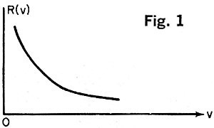
2. Linear Elements. A. Definition. A linear element is one that, if its input is increased by a given amount, responds with a proportional increase. For example, if the voltage across a linear resistor is doubled, the current flowing in the resistor is also doubled. A nonlinear resistor is shown in Fig. 1. Note that the value of the resistor, R (v), depends on the voltage across it. (In this article we are concerned only with linear elements.) B. Linear Circuits. A linear circuit contains only linear elements. 3. Notation. For DC quantities, use upper-case letters for voltage (V), current (I), energy (W), and power (P). For time-varying quantities, use lower-case letters.
A. Definition. (1) An ideal voltage source is one whose voltage, V" is constant regardless of the current it supplies. (2) An ideal current source is one whose current, I, is constant regardless of the voltage across the element to which it supplies current. B. Symbols. Symbols for ideal voltage and current sources are shown in Fig. 2. 5. Unit Step Function A. Definition. A unit step function, u-1 (t), is equal to 0 for t less than 0 and 1 for t greater than 0 (Fig. 3). This concept is useful in describing, for example, the application of a direct voltage (or direct current) to a circuit. If we let v = Vu-1(t), at t less than 0, v = 0 and at t greater than 0, v = V. If i = Iu-1,(t ), i = 0 for t less than 0 and i = 1 for t greater than 0. 6. Circuits Containing R & C and R & L Elements. A. RC Circuits. To a direct current, a capacitor acts initially (time t = 0) like a short circuit. (1) The product of R and C is called the time constant, T, of the circuit: T = RC. (2) After a time of approximately 5T, the circuit is considered to be in steady state, and the capacitor acts like an open circuit. (3) Steady state is symbolized by t = ∞. Ex. 1. For the circuit in Fig. 4, determine 1 at (a) t = 0, I(0) and (b) in steady state, 1(∞). (c) What is the time constant of the circuit? Sol. (a) I(0) = 10/100 = 0.1 A. (b) I(∞) = 0. (c) T = RC = 100 X 10 X 10-6 = 10-3 s = 1 ms. Ex. 2. For the circuit in Fig. 4, find the voltage across the capacitor, VC, at (a) t = 0 and (b) t = ∞. Sol. (a) Because the capacitor acts like a short circuit at t = 0, VC(0) = 0. (b) Because the capacitor acts like an open circuit in steady state, VC(∞) = 10 V.
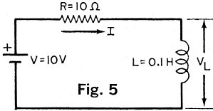
i(t) = (V/R) ε-t/RC and vc(t) = V (1 - ε-t/RC). C. RL Circuits. To a direct current, an inductor acts like an open circuit at t = 0 and as a short circuit at t = ∞. The time constant is T = L/R. Ex. 3. Referring to Fig. 5, determine the current I at (a) t = 0 and (b) t = ∞. (c) What is the time constant for the circuit? Sol. (a) I(0) = 0. (b) I(∞) = V/R = 10/10 = 1 A. (c) T = L/R = 0.1/10 = 0.01 s = 10 ms. Ex. 4. For the circuit in Fig. 5, find the voltage across the inductor, at (a) t = 0 and (b) t = ∞. Sol. (a) Because the inductor acts like an open circuit at t = 0, VL(0) = 10 V. (b) Because the inductor acts like a short circuit in steady state, VL(∞) = 0. D. Functions of Time. For times between t = 0 and t = ∞, the current and voltage as functions of time for the circuit in Fig. 5 may be expressed by: i(t) = (V/R) (i - ε-tR/L) and vL(t) = V ε-tR/L.
7. Energy and Power. A. Definitions. (1) Energy may be defined as the ability to do work. In the mks (meter, kilogram, second) system of units, the unit of energy is the newton-meter or joule. One joule is equal to one watt-second. (2) Power is the rate of doing work or the rate-of-change. of energy with respect to time. Its unit is joules/second or watts. (3) Energy, w, is equal to the product of power,. p, and time, t: w = pt. (4) For electrical circuits, p = vi. Since i = v/R and v = iR, we can write p = v2/R = i2R. (5) Only resistors are capable of dissipating energy; capacitors and inductors store energy. B. Energy Stored in Capacitor. The energy stored in a capacitor is wC = 1/2Cv2, where v is the voltage across the capacitor. C. Energy Stored in Inductor. The energy stored in an inductor is wL =:= 1/2Li2, where i is the current flowing in the inductor. Ex. 5. A 200-watt light bulb is powered by a 120-volt DC source. Find (a) the current required by the bulb and (b) the energy consumed in lighting the bulb for 2 hours. Sol. (a) I = P/V = 200/120 = 1.67 A. (b) W = Pt = 200 X 2 X 3600 = 1.44 X 10⁶ joules. Ex. 6. Determine the energy stored in (a) a 1-microfarad capacitor across which is 10 volts and (b) a 10-millihenry inductor whose current is 4 A. Sol. (a) WC = 1/2 X 10-6 (10)2 = 0.5 X 10⁻⁴ joules. (b) wL = 1/2 X 10 X 10-3 (4)2 = 0.08 joules. Note: The circuit laws, theorems, and techniques reviewed here also apply, in general, to AC circuits. 8. Kirchhoff's Laws. A. Kirchhoff's laws provide a formal method of finding currents and voltages in a circuit, regardless of its complexity. The laws apply to circuits energized by de, ac, or time-varying voltage and currents. B. Voltage Law. The voltage law states that the algebraic sum of voltages around a closed path is equal to zero. Mathematically, ∑v(t) = 0, where ∑ is the Greek symbol for sum.
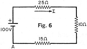
Ex. 7. Using Kirchhoff's voltage law, find (a) the current in and (b) the voltage across the 10-ohm resistor in the series circuit in Fig. 6. Sol. It is necessary to distinguish the direction of current flow and the polarity of voltage sources in the application of Kirchhoff's voltage law. The convention used here is: (1) A minus sign precedes a voltage quantity in going around a closed path from a low to a high potential or against the direction of indicated current flow. (2) A plus sign precedes a voltage quantity in going around a closed path from a high to a low potential or with the direction of indicated current flow. (3) The assumed direction of current flow is arbitrary. (a) Referring to Fig. 6, assume that we start at point A and go around the closed path clockwise (with the direction of indicated current flow). Then, according to the voltage law and the conventions we have adopted, - 100 + (25 + 10 +15)I = 0 or I = 100/50 = 2 A. (b) From Ohm's law, the voltage across the resistor is V = IR = 2(10) = 20 V.
Ex. 9. If, in Ex. 8, R1 = 1 ohm, R2 = 2 ohms, R3 = 4 ohms, and V1 = V2 = 6 V, solve for I1, I2 and the voltage across each resistor. Sol. Substituting the given values in Eqs (1) and (2), we get 6 = 3I1 - 2I2 (Eq 3) and -6 = -2I1 + 6I2 (Eq 4). Equations (3) and (4) may be solved for I1 and I2 in a number of ways. If, for example, we multiply Eq (3) by 3 and add the result to Eq (4), we have 12 = 7I1 or I1 = 12/7 A. Substituting this value in Eq (4) and solving, I2 = -3/7 A. The negative sign denotes that I2 actually flows in a direction opposite to that assumed in Fig. 7. The voltage across R1 is V = (12/7) 1 = 12/7 V; across R2, V = (12/7 + 3/7)2 = 30/7 V; and across R3, V = (-3/7)4 = -12/7 V.
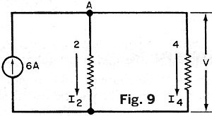
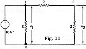
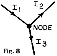
D. Current law. Kirchhoff's current law states that the algebraic sum of currents leaving a node is equal to zero, or ∑i(t) = 0. A node is a junction of two or more elements. If currents flowing toward a node are taken as negative and currents flowing away as positive, then, for example, -i1 + i2 +i3 = 0 in Fig. 8. E. Parallel Circuits. A parallel circuit is a network where the voltage across each element is the same (Fig. 9). Ex. 10. For the parallel circuit in Fig. 9, determine (a) the voltage across each resistor and (b) the current in each. Sol. (a) Applying Kirchhoff's current law at node A, we have: -6 + V/2 + V/4 = 0 or 6 = V(2 + 1)/4 = 3V/4; and V = 8V. (b) I2 = 8/2 = 4 A; I4 = 8/4 = 2 A. F. Conductance. Conductance, G, is the reciprocal of resistance; thus G = 1/R. The unit for conductance is the mho, which is ohm spelled backwards. Ex. 11. Referring to Fig. 10, write the necessary equations to solve for V1 and V2. Sol. From Fig. 10, V1 is taken between nodes 1 and N; with V2 between nodes 2 and N. Node N is a common node and nodes 1 and 2 are independent nodes. Because we have two independent nodes, two nodal equations are necessary. With the assumed currents as shown, Kirchhoff's current law for node 1 gives: - I1 + I2 + I3 = 0 (Eq. 5). At node 2: -I3 + I4 = 0 (Eq 6). Expressing Eqs (5) and (6) in terms of voltages and resistance, we have -(V - V1)/R1 + V1/R2 + (V1 - V2)R3 = 0, or V/R1 = V1(1/R1 +1/R2 + 1/R1) - V2/R3 (Eq 7); and - (V1 - V2)/R3 + V2/R4= 0 or -V1/R3 + V2(1/R3 + 1/R4) = 0 (Eq 8). Equations (7) and (8) can be expressed in terms of conductances: thus, G1V = (G1 + G2 + G3)V1 - G3V2 (Eq 9) and -G3V1 + (G3 + G4)V2 = 0 (Eq 10). Terms G1 + G2 + G3 and G3 + G4 are the self conductance of nodes 1 and 2, respectively; and G3 is the mutual conductance between nodes 1 and 2. Ex. 12. For the network in Fig. 11, determine V1 and V2. Sol. At node 1, -10 + 0.5V1 + 0.5 (V1 - V2) = 0, or 10 = V1 - 0.5V2 (Eq 11). At node 2, - 0.5(V1 - V2) + 0.5V2 = 0, or -0.5V1 +V2 = 0 (Eq 12). From Eq (12), V1 = 2V2. Substituting this value in Eq 11, we have 10 = 2V2 - 0.5V2 = 1.5V2. Solving, V2 = 10/1.5 = 6.7 V and V1 = 2V2 = 2(6.7) = 13.4 V. Fig. 11 (To be continued)
Posted February 16, 2018 |
|
 C. Voltage and Current Relations for L and C.
(1) The voltage across an inductor (L) is equal to the value of inductance (henrys) multiplied
by the rate of change of current with respect to time (amperes/second): v = L(di/dt).
If i is a direct current, it does not change with time; thereforedi/dt = 0 and v = 0.
(2) The current in a capacitor (C) is equal to the value of the capacitance (farads)
multiplied by the rate of change of voltage across the capacitor with respect to time
(volts/second): i = C(dv/dt). If v is a direct voltage, it does not change with time;
therefore, dv/dt = 0 and i = 0. This demonstrates that a capacitor blocks the flow of
direct current. (3) The charge q (coulombs) stored in a capacitor is q = vC.
C. Voltage and Current Relations for L and C.
(1) The voltage across an inductor (L) is equal to the value of inductance (henrys) multiplied
by the rate of change of current with respect to time (amperes/second): v = L(di/dt).
If i is a direct current, it does not change with time; thereforedi/dt = 0 and v = 0.
(2) The current in a capacitor (C) is equal to the value of the capacitance (farads)
multiplied by the rate of change of voltage across the capacitor with respect to time
(volts/second): i = C(dv/dt). If v is a direct voltage, it does not change with time;
therefore, dv/dt = 0 and i = 0. This demonstrates that a capacitor blocks the flow of
direct current. (3) The charge q (coulombs) stored in a capacitor is q = vC. 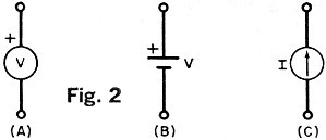 4. Ideal Sources.
 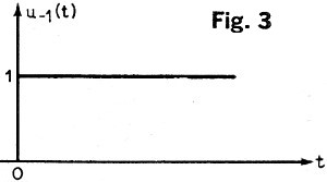 B. Functions of Time. For times between
t = 0 and t = ∞, the current and voltage as functions of time for the circuit in
Fig. 4 may be expressed by:
B. Functions of Time. For times between
t = 0 and t = ∞, the current and voltage as functions of time for the circuit in
Fig. 4 may be expressed by: 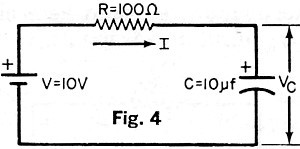

 Ex. 8. Figure 7 shows a two-mesh or two-loop network
with the assumed clockwise direction of current flow in each mesh indicated. Write the
necessary equations to solve for the two currents. Sol. For the first mesh, beginning
at point A, the voltages are -V1 + (R1 + R2)I1
- R2I2 = 0 (Eq 1). For the second mesh, starting at point B, -R2I1
+ (R2 + R3)I2 + V2 = 0 or -V2
= -R2I1 + (R2 + R3)I2 (Eq 2).
Equations (1) and (2) constitute a pair of simultaneous equations. Terms R1
+ R2 and R2 + R3 are the self resistance of meshes 1
and 2, respectively; term R2 is the mutual resistance linking the two meshes.
Ex. 8. Figure 7 shows a two-mesh or two-loop network
with the assumed clockwise direction of current flow in each mesh indicated. Write the
necessary equations to solve for the two currents. Sol. For the first mesh, beginning
at point A, the voltages are -V1 + (R1 + R2)I1
- R2I2 = 0 (Eq 1). For the second mesh, starting at point B, -R2I1
+ (R2 + R3)I2 + V2 = 0 or -V2
= -R2I1 + (R2 + R3)I2 (Eq 2).
Equations (1) and (2) constitute a pair of simultaneous equations. Terms R1
+ R2 and R2 + R3 are the self resistance of meshes 1
and 2, respectively; term R2 is the mutual resistance linking the two meshes.