|
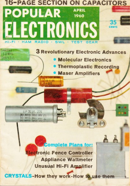
April 1960 Popular Electronics
 Table
of Contents Table
of Contents
Wax nostalgic about and learn from the history of early electronics. See articles
from
Popular Electronics,
published October 1954 - April 1985. All copyrights are hereby acknowledged.
|
The fundamentals of crystals
has not changed since this article appeared in a 1960 edition of Popular Electronics
magazine, although the way they are grown, cut, trimmed, and packaged has changed fairly significantly.
Our understanding of how they work at the atomic level has advanced significantly
as well.
Nearly every digital device in existence has at least one crystal buried inside
it for clock generation, so the number of crystals being manufactured has grown
exponentially over the intervening decades. When considering the oscillators
circuits shown here, you can mentally replace the vacuum tubes with transistors
to get an understanding of what is going on.
After Class Feature: Crystals
 Nearly everyone in electronics makes use of crystals
every day - here's why these rock-like plates play such an important role in keeping
the world in tune Nearly everyone in electronics makes use of crystals
every day - here's why these rock-like plates play such an important role in keeping
the world in tune
By Jim Kyle, K5JKX/6
An amateur radio operator, an airline pilot, a police radio dispatcher, a broadcast-station
announcer ... sound like a hodge-podge of job holders? Maybe so, but they have at
least one thing in common. All make daily use of the peculiar properties of quartz
crystals - thin, glass-like plates that keep the world in tune.
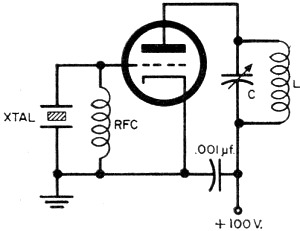
Fig. 1 - In a typical oscillator circuit, turning the oscillator
on develops a voltage between its cathode and grid, and this voltage shocks the
crystal into vibration at its resonant frequency. The vibration in turn develops
an alternating voltage across the crystal terminals, which is amplified by the tube.
The LC circuit is tuned near the crystal frequency and presents a high impedance
in the tube's plate circuit. Consequently, a portion of the amplified voltage is
fed back to the crystal and maintains oscillation.
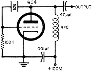
Fig. 2 - Pierce oscillator operates at almost any frequency,
but uses only fundamental frequency of the crystal. Plate voltage should be as low
as possible.
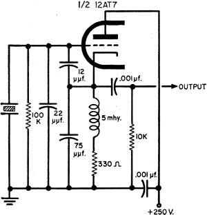
Fig. 3 - Colpitts oscillator gives good output on harmonic
as well as fundamental frequencies if LC circuit is substituted for the 10,000-ohm
resistor.
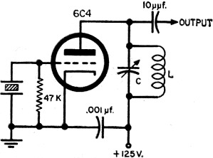
Fig. 4 - Overtone oscillator will provide output up to 60
mc. with crystals ground for third-harmonic operation. LC circuit must be tuned
to output frequency.
Crystals are found in almost all commercial and ham radio equipment, but few
of their users know how they work. Before we examine the details of crystal operation,
let's take time out to define our terms. There are three important words involved:
resonance, damping, and piezoelectricity.
Resonance means the frequency at which an object will vibrate most easily. Every
object has a resonant frequency. Musical instruments - the piano, for instance -
are based on this principle. When you strike a key, a hammer hits the piano string,
which then vibrates at its resonant note.
Damping means the suppression of an object's tendency to vibrate, The more highly
damped an object is, the less readily it will vibrate. In the piano, for example,
stepping on the loud pedal removes the damping from the strings. Stepping on the
soft pedal damps the vibrations even more than usual.
Finally, piezoelectricity is a property shared by several substances. It means
that the substance generates a small voltage across its opposite sides if it is
stretched or squeezed. In addition, applying a voltage to opposite sides of a piezoelectric
material will deform the substance as long as the voltage is present.
How a Crystal Works. Let's assume that we have a crystal of some piezoelectric
substance, and a means of making electrical contact to its opposite sides. Since
the crystal has mass, it will have a resonant frequency. If it's jarred - mechanically
excited - it will vibrate at that frequency. And if the crystal's damping is light,
it will continue to vibrate at its resonant frequency for some time.
But remember that our crystal is piezoelectric. By definition, this means that
it will develop a voltage across its opposite sides whenever it's stretched or squeezed.
The electrical contacts we've connected to those sides will allow us to utilize
that voltage.
If the crystal's size is such that the resonant frequency falls within the r.f.
spectrum - and this is ordinarily the case - we have a generator of r.f. energy.
But our generator must be" jarred to be put into operation, and it will operate
only until the vibrations die out. For it to be of use to us, we must make our crystal
operate continuously.
The addition of a special vacuum-tube or transistor circuit to amplify a portion
of the crystal's developed voltage and then feed it back to the crystal will keep
the crystal operating indefinitely. Such a circuit is called an oscillator and is
used to "jar" the crystal electrically at the proper instant to keep its vibrations
going. Before looking at several types of oscillator circuits, let's consider the
reason for using a crystal at all.
Why Use Crystals? Since oscillators can be built without using a crystal - the
ordinary superheterodyne radio receiver and the ham's VFO are good examples - the
question arises, "Why bother with crystals ?"
Actually, a crystal has only one major advantage over a well-built variable oscillator
- stability. A crystal's resonant frequency is determined primarily by its physical
size. This means that the frequency of a crystal is relatively unaffected by outside
influences.
There are, however, two outside influences which can change a crystal's frequency.
One is widely known, the other almost ignored.
The first enemy of crystal stability is heat. Like any substance, a crystal will
change in size slightly as it heats or cools - and its frequency is determined mainly
by its size. Thus, changes in temperature will be reflected as a drift in frequency.
The effect can be serious. In commercial applications, a crystal is usually kept
in a tiny oven, thermostat-regulated to maintain an even temperature. Amateur and
experimenters' crystals, in contrast, are designed to remain at a fixed frequency
under reasonable temperature variations. But overloading the crystal in an effort
to extract the last measure of power from the circuit can push its temperature into
the "unreasonable" region.
Even more serious than the heating problem - and far less widely known - is the
matter of shunt capacitance. In an ideal situation, the crystal will "see" no load
at all across its terminals. But such a circuit is impossible in practice, since
the crystal must feed an oscillator in order to operate. And, with the oscillator
connected, some capacitance is unavoidable.
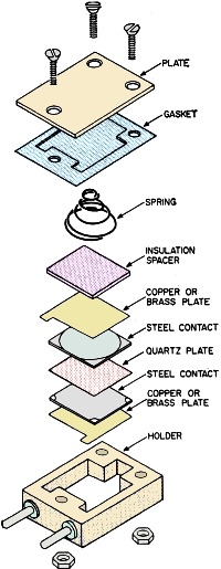
Structurally, the piezoelectric crystal used in radio transmitters consists of
a thin plate of Brazilian quartz about 1/2" square. There is a contact on either
side, and the entire unit is enclosed in a container for protection. The contacts
are held in position against the crystal by spring pressure, or, sometimes, they
are plated onto the surface of the quartz. Each contact is then connected to one
of the base pins.
This capacitance acts as a load on the crystal, slowing down its rate of vibration
and thus lowering its resonant frequency slightly. Depending upon the capacitance
in the circuit, a crystal will produce higher or lower frequencies than that specified.
Since this effect cannot be avoided, crystal manufacturers assume a standard value
of shunt capacitance and build their crystals to give specified frequency when working
into that load. For most amateur crystals, the design value is 32 μμf.
Since manufacturers can't be expected to know the capacitance involved, most
of them refuse to guarantee extremely close accuracy unless they can calibrate the
crystal in the actual circuit to be used.
Oscillator Circuits. There are a number of circuits that can be used as oscillators.
All have two things in common - a means of amplifying the crystal's output, and
a way of feeding some of that output back to keep the crystal oscillating. A typical
oscillator circuit (Fig. 1) makes use of the tube's grid-cathode voltage to
place the crystal in operation. Because the crystal is in the grid circuit, the
tube amplifies its output.
Some oscillator circuits are designed to give output only at the fundamental
frequency of the crystal - the frequency of the crystal itself. Others are built
to provide the fundamental and integral multiples of the fundamental frequency as
well. Such multiples are known as harmonics and have frequencies of two, three,
four, or more times the fundamental frequency.
Still a third variety of crystal oscillator is the "overtone" circuit. A major
difference between it and a harmonic oscillator is that the overtone circuit produces
only one output frequency - the third, fifth, or other odd harmonic. A harmonic
oscillator, in contrast, produces the entire gamut - the fundamental, the desired
frequency, and other harmonics, too.
The Pierce circuit shown in Fig. 2 is typical of a fundamental-frequency
oscillator. It operates at the crystal's fundamental frequency, without tuning or
other adjustments.
One of the most popular harmonic-oscillator circuits is shown in Fig. 3.
This is the Colpitts or "grid-plate" circuit. As shown, it produces useful power
output up to the fourth harmonic of the crystal's fundamental frequency, if an LC
circuit in the output is tuned to the desired output frequency.
There are many types of overtone oscillator circuits. The one shown in Fig. 4
is recommended by International Crystal engineers for use with their overtone crystals
in the 15-60 mc. range.
All three of these circuits are stable. Crystal heating - if operating voltages
are kept within the limits shown - poses no problem. If you keep in mind that a
crystal is intended to control frequency and not to produce power, you'll have no
trouble. Keep power input to the oscillator as low as possible, and let other stages
of the equipment provide power output.
In both the Pierce and Colpitts circuits, shunt capacitance affects the crystal's
operating frequency. Values shown for the Colpitts circuit result in about 32 μμf.
across the crystal. In either circuit, a small variable capacitor can be connected
in parallel with the crystal to adjust the output frequency slightly.
Since the overtone circuit operates differently, additional capacitance across
its crystal will have little effect on frequency. If the capacitance is excessive,
though, it may keep the oscillator from functioning.
Controlling the frequency of a radio transmitter is but one application of the
quartz crystal. Although it operates in a completely different way, a crystal is
electrically the same as an extremely efficient LC (or "tank") circuit. For this
reason, a crystal can replace a tank circuit in any low-power installation.
But the major use of quartz crystals today is in transmitter frequency control.
Here, they provide precision channels at low cost and enable efficient use of the
limited radio spectrum. In fact, these rock-like plates make radio as we know it
possible. Their purpose? Keeping the world in tune!
Posted May 14, 2021
(updated from original post on 7/13/2012
|