Calculating Input and Output Impedances
|
|
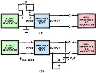
While not a precise method of determining the input and/or output impedance of black box type devices, the described voltage division method suffices for many - if not most - situations. The June 1969 issue of Popular Electronics magazine offered this process of placing a variable resistance (potentiometer) at the device under test (DUT) input and/or output and adjusting the voltage reading to be half the value without the resistor. When both the source and the load are pure resistance (no capacitance or inductance), it is safe to assume the after-adjustment value of the resistor represents the DUT impedances - that is only a real part and no imaginary part (Z = R ± j0 Ω). The precise method of determining the impedances requires a little extra work. Rather than describe it here, I refer you to a very nice c2008 paper by Mr. Kenneth A. Kuhn entitled, "A Simple Circuit for Measuring Complex Impedance." Calculating Input and Output Impedances The upper circuit (A) is used to determine input impedance, while the lower circuit (B) is used for output impedance measurements. Although not exactly "on the head", system is accurate enough for most experimenters. Simple method gives answers without complicated mathematics. When you buy or build an audio amplifier, you are given values for most of the important characteristics. Unfortunately, input and output impedances are not usually included. To get the most out of any amplifier, you need to know its input impedance so that you can match it to the output impedance of the signal generating device (preamp, mike, tuner, etc.). Similarly, the amplifier's output impedance should match the input impedance of the load (loudspeaker, power amplifier, etc.). Means of determining input and output impedances are omitted in most cases because they involve complicated mathematics and sophisticated measurement techniques. Here is an impedance measuring technique which is simple and easy to perform. Mathematics have been reduced to the bare essentials and the results, although not exact, are close enough for use by most electronics experimenters. The measurements can be made on either transistor or vacuum-tube amplifiers and they require the use of only an audio signal generator, a high−impedance a.c. voltmeter (VTVM or TVM), a potentiometer, and perhaps a capacitor. Input Impedance To measure input impedance, use the circuit shown at (A). The output level of the signal generator should be equivalent to the normal input of the amplifier and it should be set for a frequency of 1 kHz. The potentiometer should have a resistance of 10,000 to 25,000 ohms for a conventional bipolar transistor input and several megohms for a field−effect transistor or vacuum−tube input. First, short out the potentiometer (terminals 1 and 2 in the diagram). Apply the recommended input to the amplifier from the signal generator and read the output on the voltmeter as closely as possible. Without disturbing the controls of the generator or the amplifier, remove the short from across the potentiometer. (Note that one end of the potentiometer is connected to the rotor.) Adjust the potentiometer until the voltmeter indicates exactly half the previous reading. Without disturbing the setting of the potentiometer, remove it from the circuit and measure its resistance from the open end to the rotor. This value very closely approximates the input impedance (at 1 kHz) of the amplifier under test. The input impedance at any other audio frequency can be measured similarly. Output Impedance In the circuit shown at (B), the output of the signal generator is coupled directly to the input of the amplifier and the voltmeter is used to measure the amplifier output across a variable load. The resistance of the potentiometer should be up to 50 ohms for a loudspeaker load, up to 25,000 ohms if the load is a transistor power amplifier, and up to 1 or 2 megohms if the load is a tube circuit. If the amplifier does not have a capacitor−coupled output, the variable load resistor should be connected to the output through a large−value capacitor whose reactance is low at the testing frequency. Set the load potentiometer close to its maximum resistance and apply a signal to the amplifier. Record the voltmeter reading as V1. Reduce the value of the load resistor until the voltmeter reads about 10% less than before. Record this voltage as V2. Without disturbing the setting of the potentiometer, remove it from the circuit and measure the resistance between the free end and the rotor. Record this value as RZ. The output resistance can then be calculated from Z = R1/[V2(V1 - V2)]. For example, if R1 is 3000 ohms, V1 is 3 volts and V2 is 2.5 volts, the output impedance of the amplifier is 3000/[2.5(0.5)] = 2400 ohms.
Posted May 10, 2023 |
|

