Build a Numeric Glow Tube (Nixie) DCU
|
|
The mere sight of a Nixie tube evokes passion and nostalgia in the hearts and minds of vintage electronics aficionados. For the uninitiated, Nixie tubes were one of the most successful early numeric display formats. They had wire filaments shaped in the form of numerals 0 through 9, stacked front-to-back inside a vacuum tube enclosure. Rather than the filament (wire) doing the glowing, the neon gas (plus traces of others) fluoresces (glows) in the vicinity of the wire. 7-segment LED displays had not yet hit the commercial market when this story was published in a 1970 issue of Popular Electronics magazine, so even though the numeric display uses vacuum tubes (Nixie) the power supply, counter, and display driver circuits use semiconductors rather than vacuum tubes. Very extensive circuit descriptions, building instructions, schematics, and photos are provided by author Don Lancaster. If you want to build one of these vintage counters, Nixie tubes can still be bought on eBay at very reasonable prices. Build a Numeric Glow Tube DCU - Nixie Readout at $15 per Decade
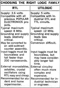
Now it is possible to build a high-speed, decimal counter module (complete with logic and Nixie® tube readout) at a cost of $14.90 per decade. This counter, with speeds from d.c. to either 8 or 12 MHz (depending on the type of logic used), can be built with 2 1/2 decades (0-199), 3 1/2 decades (0-1999), or 4 1/2 decades (0-19999) using a single printed circuit board. No mounting or front brackets are needed and there is a minimum of interconnections to be made. The design provides an overflow indicator and latch which operate when full scale is exceeded. This function is useful for overrange indication or as a "turn-around" command on dual-slope DVM designs. Display blanking, in which the readout can be turned off or on by an external 0-2-volt d.c. control signal is also available. This feature eliminates display bobble or blur and back-and-forth numeral motion during rapid counting. There is also a self-contained "gate" input that permits turning the counters on and off and is useful for period or frequency measurements. This feature eliminates quite a bit of external circuitry. You have a choice of the type of logic you use in building the DCU. If RTL is used, the unit is fully compatible with previous POPULAR ELECTRONICS projects. Or you can use Utilogic® (Signetics Corp.), a faster type of logic with a higher voltage swing that is compatible with industrial TTL and DTL circuits. Both types of logic cost the same.
The IC counters are "weighted" in the industrial 1-2-4-8 manner to provide electrical as well as visual outputs if de-sired. A simple modification and an external adapter can be used to convert the RTL version of the DCU into an "add-subtract" counter which operates in either direction. The units are useful in computers, calculators, and positional controls. When RTL is used in this new DCU, the unit can be used in POPULAR ELECTRONICS projects such as the "Digital Volt-Ohm-Meter," the "Universal Frequency Counter," the "Sports Timer," and the "Electronic Stopwatch." In fact, with a few mechanical changes, the new 2 1/2-digit assembly can be dropped into the "Digital Volt-Ohm-Meter" without adding any new parts. This makes a DVM that looks like the industrial models that cost many times as much. Because of space limitations, construction details are given here for the RTL counter only. Complete information, including PC layouts, for the Utilogic version is available without cost from the source given in the box. In deciding whether you want to use RTL or Utilogic in your DCU, consult the Table. The circuit for one decade of the DCU is shown in Fig. 1 and that of the overflow counter is shown in Fig. 2. Although these are shown as separate circuits, in practice, one overflow counter and as many decades as are necessary are mounted on one PC board. Interconnections for the units are shown in Fig. 3. Note that the Gate connections of all decades except the first are grounded. In this way, if the input (units) decade is turned on or inhibited, the counter operates or not accordingly.
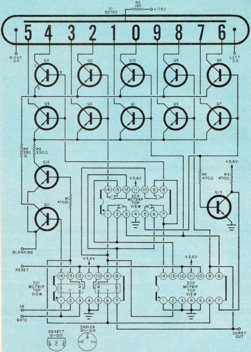
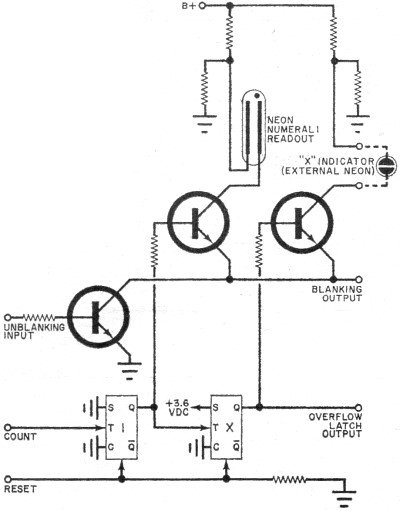
Fig.1 - The schematic for one decade counter. As many decades as desired can be built using this same schematic. The readout is a conventional Nixie tube with a glowing numerical-shaped display.
Fig. 2 - The overflow counter is coupled to the last decade used. When an excess count is received, power is applied to the external overrange (neon) indicator.
Fig. 3 - Underside view of the PC board showing how some jumpers are connected. These below-board jumpers must all be insulated.
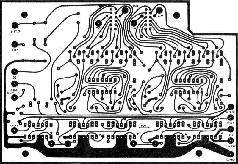
Fig. 4 - Actual-size pattern for the 2 1/2-decade board, with associated overflow counter. By judicious re-arrangement of the foil pattern the number of decades used can be extended. Boards for multi-decade readout can also be purchased.
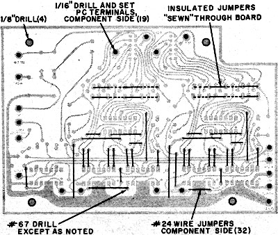
Fig. 5. Board drilling and jumper installation. Some jumpers are "sewn" through the board as illustrated above. Start at one end, and pass the wire through the respective holes, inserting the insulation at the required places.
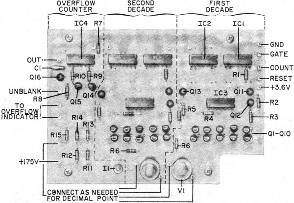
Fig. 6 - Component installation of 2 1/2-decade board. Other than placement of R6, both decades are similar. This illustration shows external connections needed.
The 2 1/2·decade board. Each Nixie indicates up to 9, and at the 100th count, both Nixies indicate zero while the special-"1" neon lamp comes on. The combination indicates to 199. At 200th count, a special over-range neon lamp (not shown) glows indicating that counter has progressed beyond its limits. Decade counter schematic.
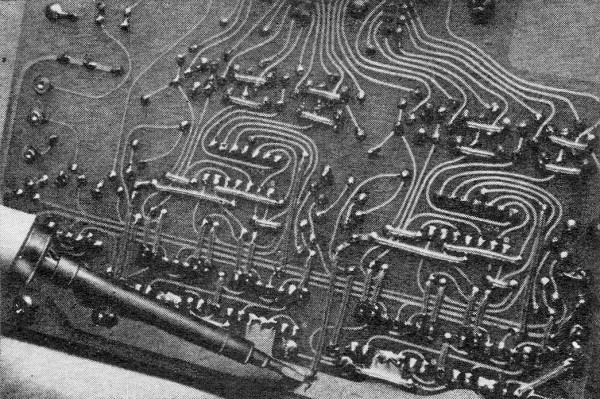
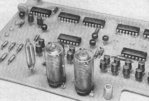
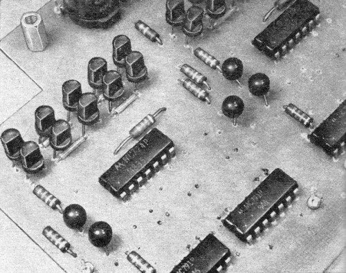
General view of a portion of a 2 1/2-decade board. This view shows the correct way to install the ten switching transistors for the Nixie drive.
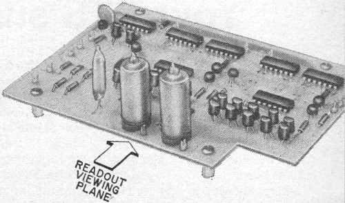
Overall view of the 2 1/2·decade board. When mounted in enclosure, only the readouts will be visible.
General view of the second decade of the counter. Even though the three portions extend across the board, the three readouts are very closely spaced.
Fig. 7 - Low-ripple power supply for the 2 1/2-decade board. By changing D4, the supply can be used for either RTL or Utilogic circuits.
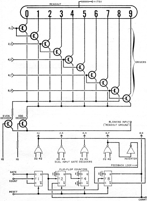
The overflow counter consists of a counting section, a display driver, and a display. Construction Decimal counting units can be built in a number of configurations: 1 1/2 (counting to 19), 2 1/2 (to 199) , 3 1/2 (to 1999), 4 1/2 (to 19999), etc. In each case the 1/2 stands for the "1" of the overflow counter, while the whole number stands for the number of decade counters (each counting to 9). Construction details are given here for the popular 2 1/2-digit assembly. Because of the complexity of the circuit, a printed board is mandatory. A board is shown actual-size in Fig. 4. A commercially made board is available (see Parts List for Fig. 1). If you prefer to make your own, it is recommended that you use the better-grade, G-10 fiberglass. Parts List - Decade Counter IC1,IC2-MRTL dual JK flip-flop (Motorola MC791P) IC3-MRTL quad two-input gate (Motorola MC724P) Q1-Q10-2N3877 transistor (Allied Electronics 49D30 2N3877 SPR, no substitute) Q11-Q13-Transistor (National Semiconductor 2N5129) R1,R4,R5-470-ohm; 1/4-watt resistor R2,R3-330-ohm, 1/4-watt resistor R6-15,000-ohm, 1/4-watt resistor V1-Nixie tube (Burroughs B5750) Misc.-#24 wire jumpers, insulated sleeving, solder, spacers, mounting hardware, etc. Note The following are available from Southwest Technical Products, Box 16297, San Antonio, Texas 78216: Etched and drilled PC boards-2 1/2-digit, $4.00; 3 1/2-digit, $5.75; 4 1/2-digit, $7.50. Complete kit of all parts- 2 1/2-digit, $43.50; 3 1/2-digit, $59.50; 4 1/2-digit, $75.00. Write for a complete list of related circuits, kits, and instruments. All prices post-paid in U.S.A. Besides drilling details, Fig. 5 shows the location of the 32 jumpers located on the component side of the board. In addition, there are four jumpers that are "sewn" through the board, so that they alternate from one side to the other and pick up five connections each. Details of this are also shown in Fig. 5. The long bare jumper is soldered at one end and then threaded through the holes in the board. Use insulated sleeving over the exposed parts to prevent shorts to the transistor leads. Once the various jumpers have been installed, the components are inserted in accordance with the layout shown in Fig. 6. Use a low-power (40-watt) soldering iron and thin solder to make all connections. The IC's are identified by a notch and dot code for positioning. To insert the 20 driver transistors, hold them with the flat facing away from the readout tubes. Then bend the center lead back toward the tubes and insert as shown. In inserting the Nixie tubes, put the leads in two at a time. Before soldering, make sure that all leads are tight, none are doubled over or shorted to each other and the viewing face of the tube is aimed in the correct direction. Also be certain the tube is vertical. Mount the neon lamp (for numeral 1) so that the metal rods within the tall narrow bulb are at the same height as the numerals in the Nixie tubes. Use. The 2 1/2-digit module can be used in anyone of a variety of chassis styles - as long as it has a rectangular front-panel cutout for the two Nixie readout tubes and the neon light. A special polarized optical filter is available (see Parts List for Fig. 1) to improve readout visibility. This filter should be oriented to produce the blackest instrument interior when viewed and illuminated through the filter. Once the correct orientation has been found, glue the filter in place behind the front-panel cutout. External connections to the module are shown in Fig. 6. The 2 1/2-digit module requires +175 volts at 5 mA for the readouts, and + 3.6 volts at 340 mA for the remainder of the circuit. A power supply (such as the one shown in Fig. 7) is required. It has low ripple with high-frequency bypassing - an essential. Ground leads should be short and of heavy gauge wire (at least #16). The "Out" terminal on the board is used only in some special DVM circuits and is normally left unconnected. The terminals along the rear of the board are for use in the future with an add-subtract adapter and are also left unconnected for routine applications. The "Gate" input, if used, goes to an RTL-derived signal that is positive when the counter is to be inhibited and ground when the counter is to count. If you are not going to gate the assembly, the Gate terminal should be connected to the ground terminal For UTI Logic DCU Details Complete construction information, including full-size PC layout replicas and all other details, is available free upon request from: Alvin R. Smith, Section Head Digital Design Group Southwest Technical Products, Inc. Box 16297 San Antonio, Texas 78216 Please limit free requests to single copies. To provide a blanking feature, connect the "Unblank" terminal to an RTL-derived signal that is positive when you want the display to light and ground when you want it off. Remember that the Unblank input does not stop the counter from working - it just determines whether or not the display can be seen. If you do not want to turn the display off, connect the Unblank terminal to the +3.6-volt source. The two terminals marked "X" are connected to a neon overrange indicator (usually mounted in a red holder). If you don't want the overrange indication, leave these two terminals unconnected. Decimal points are activated by connecting the selected decimal point terminal beside each Nixie tube to the "DP" terminal on the overflow counter through an external switch. Decimal point operation is independent of display blanking. The "Reset" terminal is normally connected to ground through an external switch. Raising the buss to +3.6 volts momentarily resets the assembly to zero. The Reset button need not be bounceless. If you use an electronic reset, a 2-microsecond pulse with a fanout of 30 is required. Input The input must be a waveform that changes abruptly from +3.6 volts to ground each time a count must be registered. For the counter to operate properly, the input must be both noiseless and bounceless and have a fall time less than 0.2 microseconds. Thus it is absolutely mandatory that the input be properly conditioned. Four possible signal conditioners are shown in Fig. 8. Circuits (A) and (B) are used for mechanical-contact inputs, while (C) and (D) are for electronic inputs. Circuit C (C) is used for input levels of about 2 volts r.m.s. If the input frequency is below 1500 Hz, the capacitor must be included. For higher frequencies, omit the capacitor. Circuit (D) is a Schmitt squaring circuit. Any of the circuits used in previous POPULAR ELECTRONICS DCU projects have the proper conditioning circuits built in. Thus, if you have built or are considering building the Digital Volt-ohmmeter (December 1968), besides making the mechanical modifications that are necessary to use this new counter module, connect the "Unblank" input to the existing "Gate" terminal on the V/F module in the Voltmeter. Should the brightness of the display be inadequate, the original DVM transformer should be replaced with the one called for in Fig. 7. Power Supply. A recommended power supply with sufficient regulation is shown in Fig. 7. This supply is wired point-to-point after all parts have been mounted in a suitable chassis. Parts List - Power Supply C1-100-µF, 250-volt electrolytic capacitor C2-6000-µF, 10-volt electrolytic capacitor C3-200-µF, 6-volt electrolytic capacitor C4-0.1-µF, 10-volt disc ceramic capacitor D1,D2-1-ampere, 600-volt silicon diode (1N4005 or similar) D3-1-ampere, 50-volt silicon diode (1N4001 or similar) D4-4.2-volt (RTL) or 5.6-volt (Utilogic) 1-watt Zener diode F1-0.5-ampere fuse and fuse holder Q1-2N5190 transistor and suitable heatsink S1-Power switch (usually a part of other instrument or circuit switching) T1-Power transformer; secondary 135-0-135 V at 50 mA, 6.3 VCT at 1 A (Southwest Technical #TR-DVM or similar)* Misc.-Mounting spacers, hardware, wire, solder, terminals, line cord and strain relief. *Available at $6.50 plus 4 lb postage from Southwest Technical Products, Box 16297, Sail Antonio, Texas 78216. How It Works - Decade Counter One decade counter can be divided into four sections: the actual counter, the decoder, the readout driver, and the readout. The counting portion (at bottom of diagram) consists of four JK flip-flops arranged to count to 9 before reverting back to zero and simultaneously delivering a "Carry" output to the next decade. To force the counter to count only to 9, an inverter in a feedback loop is used. The voltage levels, which are unique for each count, are taken from the Q and Q outputs of each flip-flop for use in the decoder. The flip-flop outputs are in the common 1-2-4-8 code. If more than one module is to be used in an instrument, the "Gate" input terminal of the counter is connected to ground in all but the first counter. When the gate is grounded, the counter operates normally. When it is made positive, the counter is inhibited. In this way, an externally generated signal can be used to determine when the counter is to operate. In the decoder, consisting of four gates and two discrete transistors, the 1-2-4-8 output of the counter is converted into a biquinary (divide by 2, then by 5) code. It has seven outputs: even, odd, 0 and 1, 2 and 3, 4 and 5, 6 and 7, 8 and 9. These form the input to the readout drivers. The readout (Nixie tube) is a gas filled tube with one common anode and 10 discrete metal cathodes, each formed into the shape of a number (from 0 to 9). When B+ is applied to the common anode and any of the cathodes is grounded, the gas around that particular piece of shaped metal glows causing a number to appear in the viewing plane. The readout drive consists of 10 high voltage transistors, driven in pairs by the decoder outputs. The transistor collectors are connected to the 10 cathodes of the Nixie tube. The emitters of all of the odd-numbered transistors are connected together and to the "odd" buss, while the even-numbered transistors have their common emitters connected to the "even" buss. The even and odd busses are driven by the two transistors in the decoder. The system can be considered to operate like a switching network. When, for example, the even transistor in the decoder is saturated (with its emitter grounded), the even buss is essentially at ground. Then, if a signal is applied to the bases of one pair of driver transistors, only the one whose emitter is connected to the even buss saturates and acts as a switch to close the circuit to the appropriate cathode on the readout. Suppose, for instance, that the count is 7. Since 7 is an odd number, the odd decoder transistor is saturated and the odd buss is grounded. Simultaneously, the 6 and 7 output of the decoder applies signals to the 6 and 7 driver transistors. Because only the 7 transistor is connected to the grounded odd buss, only the 7 transistor saturates, causing the number 7 to glow in the readout. Note that we said previously that the odd or even buss must be grounded for the decoder transistors to work. The grounding is made external to the counter through a connection to the "Blanking Input" terminal. A circuit in the overflow counter determines when this terminal is grounded for display viewing. In this way, rather than have a blur of numbers while the counter is counting, the blanking input keeps the display off until the counting is complete. Then a steady display is shown. How It Works - Overflow Counter
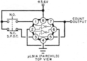
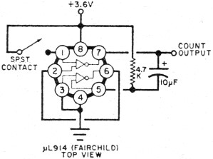
(A) Set-Reset Pushbutton Conditioning
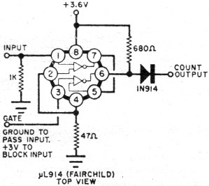
(B) Monostable Contact Conditioning
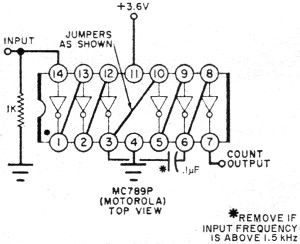
(C) Hex Inverter Input Squaring Circuit
(D) Schmitt Trigger Input Squaring Circuit Fig. 8. Four approaches to "bounceless" signal conditioners. Parts List - Overflow Counter C1-0.1-µF, 10-volt disc ceramic capacitor 1C4-MRTL dual JK flip-flop (Motorola MC 791P) Q14,Q15-2N3877 transistor (no substitute) Q16-Transistor (National Semiconductor 2N5129) The counter contains two JK flip-flops the first of which is a divide-by-two and the second a latch. The latch flips positive and stays positive when there is an overflow. Resetting the counter resets the latch. The outputs of the flip-flops drive high-voltage transistors which act as switches in series with special neon lamps. The first flip-flop and its transistor energize the neon lamp that displays a 1 which is similar to the 1 displayed by the Nixie tube. The lamp driven by the second flip-flop and its transistor is a standard neon lamp on the front panel and it indicates "Overrange." Resistors in the B+ circuit of the neon lamps provide for differences in breakdown voltages. The emitters of both driver transistors are connected together and to the "Unblank Input" through a switching transistor. A positive input to this terminal saturates the switching transistor and causes the display to turn on. The switched signal is supplied to the decimal counters through the "Blanking Output" terminal. Remember that counting continues whether or not the display is lit. The blanking merely controls whether or not the display is on. The overflow counter also contains a bypass capacitor for the supply, resistive loading for the reset buss, and a decimal point resistor. These elements are connected to their respective circuits through the instrument wiring. Either A or B can be used for mechanical switching, while either C or D can be used if the input signal comes from a conventional audio generator.
Posted July 8, 2021 |
|

 By Don Lancaster