After Class: Working with Thermistors
|
|||
A good primer on the physics behind and use of thermistors was published in the November 1956 edition of Popular Electronics. Thermistors are fundamentally substances that exhibit a large change in resistance for a given change in temperature, called temperature coefficient of resistance (TCR, or RT). Standard resistors would ideally maintain the exact same resistance regardless of temperature, but in reality most resistor types increase in resistance with an increase in temperature; i.e., a positive TCR. Most thermistors have a negative TCR, which makes them useful for cancelling out resistor temperature sensitivity. Thermistors are also used for temperature sensing and measurement, although thermocouples generally do a much better job for that application. After Class: Working with Thermistors
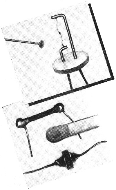
Common shapes in which thermistors are made. The head of a pin (top) is gigantic compared to tiny bead thermistor (A33 VECO) in center of fine wire. In the bottom square, a 51 R2 VECO rod thermistor and a small disc thermistor are contrasted with ordinary paper match head.
Just what is a thermistor? All electrical conductors show a tendency to change electrical resistance as their temperature varies. Some materials such as the alloy "Invar" do this so slightly that they are said to have virtually zero temperature coefficient of resistance; metallic oxides used in today's commercial thermistors change resistance abruptly with relatively small temperature variations. Modern thermistors have large negative temperature coefficients. This means that their electrical resistance drops sharply when the temperature rises. The extent of the change can be predicted quite closely from the thermistor ratings - as you will see. Forms of Fabrication. The most common physical shapes in which modern thermistors are fabricated are rods, beads, discs, and washers. Each unit starts life as a pasty black mix of several metallic oxides. Rods, discs, and washers are made by first shaping the mix paste as desired and then firing the forms in temperature-controlled ovens. The "cold" resistance of an individual thermistor is governed by the composition of the original mix and by the time-temperature constants in the sintering process. This control permits a range of 5 to 100,000 ohms at 25° C by means of only two different mixes. Manufacture of microscopic bead thermistors is a fascinating process to watch. (See Fig. 1.) Two extremely fine platinum wires (A) are held taut and parallel to each other on a special frame, the distance between wires being less than 0.005". Tiny blobs of the mix are then daubed on the wires (B) so that they are bridged by the bead; after drying and shrinking, the strand of beads is sintered and glass-coated. Later, the wires are cut to precise lengths (C) and the units are mounted on holders. Bead thermistors are available in an assortment of values from about 500 ohms to 12 megohms at 25° C. Varying Temperature. To take advantage of a thermistor's characteristics, its temperature must be made to vary and the resulting change of resistance put to use operating a meter, relay, etc. There are three distinct means by which this is done.
Fig. - Process of manufacturing microscopic bead thermistors. See text for details.
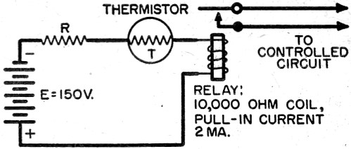
Fig. 2 - Basic circuit of thermistor fire alarm.
Fig. 3. - Resistance-temperature curve for a 51 R2. (1) Ambient temperature changes. A thermistor will follow the changes in ambient temperature by varying its resistance accordingly. This is the basis of thermometers, fire alarms, and thermostats. (2) Self-heating action. If the current through a thermistor is made large enough, the thermistor temperature will rise, causing the resistance to drop, which in turn allows more current to flow and more heat to be generated. The build-up process continues until the temperature of the thermistor stabilizes at the point where the surrounding medium can carry heat away as fast as it is generated. This action is used in flow meters, anemometers, liquid level gauges and controllers, and thermal conductivity measurement. The type of medium or its motion causes more or less rapid cooling of the self-heated thermistor, thus setting up the current-change conditions needed for measurement or control. (3) Independent heater. Some special thermistor assemblies are provided with a heating element near the temperature-sensitive bead to permit heating control independently of the main circuit current or ambient temperature. This arrangement is used only in highly specialized industrial applications. Victory Engineering Corp. Thermistor Ratings. A sensible approach to thermistor experimentation requires understanding of thermistor ratings and the circuits for which they are best adapted. Let's see what some of these are. An arrangement wherein a thermistor is connected in series with a voltage source, a variable or fixed resistance, and a relay makes up a fire alarm or other temperature relay control. The significance of the ratings in the manufacturer's data book are best explained by referring to Fig. 2 (page 77) and the text which follows. Here are the ratings for the 51R2 (tolerances are omitted for simplicity). Ro @ 25° C 100,000 ohms Dissipation constant. 2.5 mw. per ° C Time constant 20 seconds Ro @ 0° C/Ro @ 50° C 9.1 Nominal resistance (Ro). This is the nominal resistance of the thermistor at 25° C (77° F). It is the basis from which all circuit plans start and may be called the reference value at "room temperature." Dissipation constant. This refers to self-heating action. To raise the temperature of a 51R2 thermistor from, say, 50° to 51° C, the current flowing in it would have to be increased. The increment would have to be such as to cause 2.5 more milliwatts to be dissipated at the new temperature. Dissipation constants are very dependent upon the type of mounting and the surrounding medium. Consider a thermistor for which the dissipation constant is specified as 2.5 mw./° C when the thermistor is suspended by its leads in still air. If it is to be used as a thermometer which must have a maximum error of 1/2° C, then the maximum power in the thermistor must be limited to 1.25 mw. (2.5 X 1/2 = 1.25). This limitation is required since the thermistor will self-heat by 112° C when subjected to still air environment while the self-heating in moving air or liquid may be negligible.
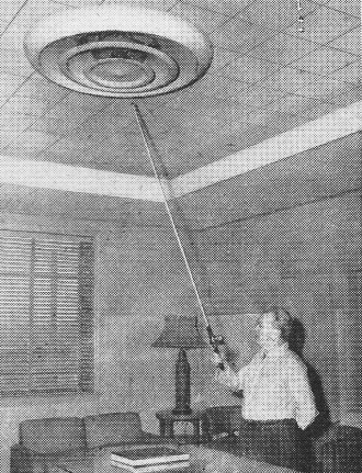
Probe attachment on thermistor thermometer is being used to measure soil temperature for agricultural control.
Inaccessible places are easily reached by a long probe like the one utilized above in measuring air-conditioner vent temperature. Time constant. There is a lag between the time that a current increase occurs and the time that the thermistor reaches the final temperature for the new current. The heating and cooling curves are so similar to those which apply to the charging of a capacitor through a resistor that we can use one as an analogy for the other. The RC time constant tells us how long it takes a given capacitor to charge to 63% of the full voltage through a specific resistor. Similarly, the thermistor time constant specifies the number of seconds required for the thermistor to attain 63% of the rise in temperature it will undergo as a result of the new current. In the case of the 51R2, the time constant is 20 seconds. Assume that a 51R2 is self-heated to 30° C and a current increase is initiated which will cause the thermistor temperature to go to 40° C, given sufficient time. It will take the thermistor 20 seconds to cover 6.3° C, i.e., 63% of the 10° C increase. Therefore, at the end of the time constant period of 20 seconds, the 51R2 will have reached a temperature of 30° + 6.3° or 36.3° C. Essentially, both the dissipation constant and the time constant depend upon how rapidly the thermistor can absorb heat from and liberate heat to its surroundings. Altering the mass of the thermistor affects both; i.e., if the mass is increased, the dissipation constant is increased and a larger time constant results. Temperature-resistance ratio (Ro @ 0° C/Ro @ 50° C. This ratio provides information related to the resistance variation which may be expected for a given thermistor as its temperature changes. For the 51R2, the resistance at 0° C is 9.1 times greater than the resistance at 50° C. This constant is an indication of the sensitivity of the thermistor to ambient temperature variations. Determining Resistance. Although there are mathematical tools available which enable engineers to determine the resistance of a thermistor at any temperature, the formulas are too complicated to be given here. From a data table supplied by the manufacturer, however, any thermistor may be calibrated by means of a curve such as that of Fig. 3. With it, we can find the resistance of the 51R2 at any temperature between 0° C and 50° C (32° F to 122° F), a very useful range indeed. As a check, note that the curve shows the resistance of the thermistor to be 100, 000 ohms at 25° C, which agrees with the nominal rating Ro given previously. Note also that the resistance at 0° C is 327,000 ohms and that at 50° C it is approximately 36,000 ohms. This verifies the temperature-resistance ratio of 9.1 (36,000 X 9.1 = 327,000 ohms). A number of practical thermistor circuits and designs will be presented in After Class in a forthcoming issue. Devices using thermistors were described in "Safeguard Your Home with a Thermistor Fire Alarm" (March, 1956, issue of POP'tronics) and "Make Your Own Electronic Thermometer" (April, 1956). Look for an article on a "Thermistor Anemometer" scheduled to appear in the near future.
Posted April 6, 2022 "After Class" Topics
|
|||

 With transistors enjoying the spotlight in current
experimental work, we tend to forget that there is another kind of semiconductor
material - the thermistor - which is finding wide acceptance in all kinds of electrical
jobs.
With transistors enjoying the spotlight in current
experimental work, we tend to forget that there is another kind of semiconductor
material - the thermistor - which is finding wide acceptance in all kinds of electrical
jobs.