After Class: What Is a Servomechanism?
|
|||
After Class: What is a Servomechanism?
Before the age of electronics, machinery was controlled directly by the hands of the operator-hands which would shift a gear, pull a lever, or apply a brake. Today's machinery is controlled by the push of a button or the twist of a knob, and many measurements and decisions are made automatically by electronic circuits. Wherever electronics and machinery work together we are apt to find some kind of servomechanism in operation. An automobile driver is the human counterpart of a servomechanism - he watches and controls a machine. As he steers his car along a winding highway, he constantly makes small corrections on his steering wheel to keep the car on the road. His eyes measure distances, his brain makes simple decisions, and his arm muscles exert corrective pressures on the steering wheel. A servomechanism performs the same function, but it is faster, more sensitive, does not make mistakes in judgment, and operates continuously. The definition of a servomechanism recommended by the Feedback Control Committee of the American Institute of Electrical Engineers is: "A feedback control system in which the controlled variable is mechanical position." Let's examine, in practical terms, what that means. The ABC's of Servos Consider our automobile driver again. From his reactions we can determine the requirements of a machine that could capably replace him. Before the start of the drive, he accepts the fact that the road divider must always remain from six to fifteen inches from his front left wheel if he is to navigate the highway turns and straightaways safely. During the trip, he must be aware of the separation that actually exists during every instant of time. Then he must compare the actual separation between his wheels and the white line with the desired separation that was initially stipulated. This might be called the error in the car's path at that instant. Once the error is determined, he must then dictate a corrective order to his arm muscles so that they can apply a force in the proper direction to eliminate the error.
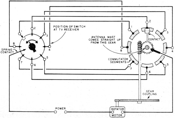
Fig. 1 - Example of an "open-loop" type servomechanism. It serves practically as an antenna rotating mechanism for TV installations. "Open-loop" refers to the need for a human control element in the servomechanism system.
Fig. 2 - A course control system as used in ocean-going vessels is a typical application of a "closed-loop" type of servomechanism. Once the course has been set, no further human guidance or readjustment is needed for operation. If we now analyze these steps, we can state the ABC's of servos. A servo must: (A) Accept instructions that tell it what should be done; (B) Be aware of the actual conditions that exist at every instant; (C) Compare what is being done with what should be done; (D) Dictate orders that will correct the error noted by this comparison; and (E) Energize some mechanism that can follow these orders. Open-Loop System Consider the antenna rotator servo shown in Fig. 1. This is referred to as an "open-loop" servo system because a human operator is required as one of the links in the ABC chain. The knob at the TV set is secured to a disc in contact with all the contact points save the one that happens to be in line with the notch cut in the disc. A permanent spring contact is made to the disc as shown. Suppose the TV viewer decides that he would like to rotate his antenna from position 2 to position 1. He turns the knob to position 1, bringing the notch in line with contact point 1 at the same time; but when he does this, contact point 2 touches the disc and feeds electrical energy to the motor through commutator segment 2. Each time the commutator arrives at a new segment, the power flows uninterruptedly to the motor until it reaches segment 1, when the circuit is again opened and the motor stops, leaving the mast in the desired position. Note that the human operator must dictate the necessary instructions to the servo by rotating the positional switch to the desired setting. In a "closed-loop" system, a human operator is totally unnecessary. Closed-Loop System Imagine that the course of a ship is to be due west and that its gyro-compass has been set for this direction. Along comes a gust of wind or an ocean current that tends to swing the prow of the ship to the north. The gyro-compass, of course, continues to point to the west as the boat turns under it, thereby producing an error angle between itself and the boat's axis. If the compass is coupled to an electrical generator of a suitable type which can feed an error signal proportional to the error angle to a rudder motor at the stern, then the rudder will swing over to an extent that will just correct the deviation from the proper course. The error angle represents the comparison between what is actually being done and what should be done. Corrective orders are dictated by means of an electrical signal that varies with the amount and direction of the error; this order signal then energizes a rudder control motor which makes the necessary correction in course. Thermostat Control When you set the thermostat of your oil-burner, you have issued instructions that it keep the house at, say, 70°F. The bi-metallic strip inside the thermostat retains "awareness" of existing temperatures by bending toward an electrical contact as the house cools. When the contacts finally close as the temperature goes below 70°F, the thermostat issues a corrective signal in the form of a current to the relay of the oil burner. If you would like to experiment with thermostatic control to get the "feel" of the ABC's of servos, you can pick up an old fluorescent starter and use it as the base for a thermostatically controlled chick incubator or a transmitter crystal oven. Pry up the four sheet-metal fingers that secure the disc base to the metal casing and lift out the whole inside structure. If a capacitor is present (some starters omit the capacitor), clip it out by cutting its leads close to the disc base.
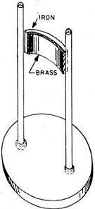
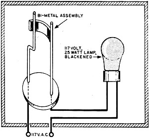
Fig. 3. - Modification required to convert a fluorescent lamp starter into a sensing element of a thermostatic control circuit. "Before " view (left) shows internal assembly of starter after protective glass is broken. "After" view (right) illustrates modification made to the contact to enable use of the starter as a thermostatic switch. Wrap a single layer of cloth around the glass tube, place it between the jaws of your vise, and apply pressure gradually until the glass just cracks. Be careful not to damage the bi-metallic assembly that is now exposed. The concave portion of the curved strip is brass and the convex section iron. Since brass has a higher coefficient of linear expansion than iron, this bar will tend to straighten when heated, i.e., it is normally off and makes contact when its temperature rises. To reverse this action, bend the free vertical bar as shown in Fig. 3 so that the inner brass face of the strip barely touches the bent bar at room temperature. The temperature at which contact will be broken will then depend upon the extent to which the strip presses on the vertical bar. This can easily be adjusted experimentally by further bending either to the right or left. An incubator or oven thermostat may be set up easily using the circuit of Fig. 4. The "heater" is a 25-watt incandescent lamp blackened with candle-black or sprayed lightly with flat black lacquer. The enclosure in which it is placed should be fairly well insulated so that it retains its heat.
Fig. 4 - Wiring and installation of modified bi-metallic element in a homemade experimental thermostatically controlled incubator or crystal (oscillator) oven.
Posted September 2, 2020 "After Class" Topics
|
|||