After Class: Power Transformers & Electrostatic Speakers
|
|||
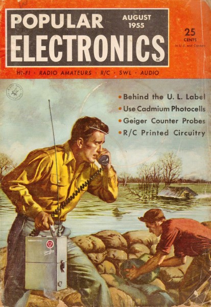
Basic transformer circuits have not changed in the more than sixty years since this article was published in Popular Electronics magazine. The applications have definitely changed, though, since active circuits of the day required a relatively low voltage (step-down) for vacuum tube cathode heaters, and at least one relatively high voltage (step-up) for biasing the tube plate. Most transformers for today's consumer applications perform a single step-down operation for 3.3 V, 5 V, 12 V, etc. In many applications, transformers are done away with altogether in favor of solid state rectifiers and regulators. A 5-question quiz is provided at the end. There is also a short tutorial on electrostatic speakers and some analog and digital signal info. Digital circuits were still a relatively new (and scary) concept to most people at the time. After Class: Power Transformers The hum of a transformer is a song of leashed power held in check by the skill of design and construction engineers. In some transformers it signals lethal voltages lying in wait for the first incautious move; in others it tells of gentle voltages applied to delicate tube filaments. In any case, we can learn to handle this versatile component by becoming familiar with the basic rules that govern its operation.
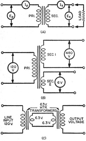
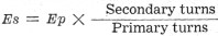
Transformer primary and secondary configurations. A power transformer-the simplest kind - consists of two separate coils of insulated wire wound around a common core of silicon steel or some similar material that concentrates magnetic lines of force. As a fluctuating voltage (Ep in Fig. A) is impressed across the primary (pri.) coil, the pulsating magnetic field that results from the flow of primary current (Ip) cuts through the secondary turns (sec.) inducing a new voltage (Es) in this winding. If a load that can consume electrical power is connected as shown, then a secondary current (Is) flows through the load. In modern power transformers, practically all of the lines of force produced by the primary current, cut through the secondary winding; this is a matter of proper design and materials. When it occurs, the windings are said to be "closely coupled," a condition that results in most efficient operation. It should be pointed out that transformers operate only on alternating current, since the process of inducing a voltage in the secondary winding depends on a change in the magnetic lines of force. Don't let anyone talk you into trying to locate a d.c. transformer! Most of the electrical power in this country has a frequency of 60 cycles per second, although some 25-cycle power is still in use in various localities. The secondary voltage, Es, may be found by applying this simple formula:
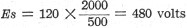
Suppose we have a transformer whose primary has 500 turns closely coupled to a 2000-turn secondary. What secondary volt-age may we anticipate if the input to the primary is 120 volts? Substituting in the formula above:
Thus, this is a step-up transformer which boosts the input voltage to four times its original value. The fraction 4/1 is called the S:P turns ratio. Evidently, from the example given above, the turns ratio is equal to the fraction "Secondary turns/Primary turns" and may be used in place of it in the equation, so that: Es = Ep x turns ratio Take another example: a filament trans-former (a step-down type) designed to operate on 120-volts primary input has a turns ratio of 1:20 (another way of writing 1/20). What secondary voltage will it produce? Using the second formula:
By exercising care in the design of the windings and the choice of the core, both transformers described in the foregoing paragraphs may be combined to form a standard multiple winding type as shown in Fig. B by winding both secondaries on the same frame as the primary. Contrary to the convictions of many beginners, transformers don't give you something for nothing. Although it is true that a transformer can step up voltage, in the process of so doing it balances the score by taking more current from the lines than it provides to the load. No transformer can ever supply more power to the load from the secondary winding than is put into its primary winding. Under ideal conditions of 100 % efficiency, the secondary power may equal the primary power, but it can never exceed it. Ignoring power factor (to be discussed in a future issue) : Ep x Ip = primary power Es x Is = secondary power Thus: Ep x Ip = Es x Is This last equation can be rewritten as: Ip = Is x Es/Ep and may be used to find the amount of primary current that will be necessary to provide a given secondary current to a load when a given transformer is used. For instance, consider our first example of a transformer having a turns ratio of 4/1. Assume that this device is to operate a radio set which acts as a 100-milliampere load. How much primary current must flow to supply this current at 480 volts in the secondary? Ip = 100 x 480/120 Ip = 100 x 4 = 400 ma. Therefore, as the transformer quadruples the input voltage by its step-up action to provide an output voltage of 480 volts, the current taken from the lines by its primary winding is four times greater than that provided for the load's use. This "balancing" action is completely automatic and is dictated by a natural law of physics called "the conservation of energy." If we could invent a transformer that would provide more secondary power than that consumed by its primary, perpetual motion would be the easy step! The following quiz is intended as a self check. All of the questions can be answered correctly if the foregoing text has been mastered. Answers below. Power Transformer Quiz 1. Radio sets made in this country and shipped to Great Britain are usually accompanied by transformers to permit the use of the 110·volt radios on 220-volt lines employed in the latter country. What must be the S:P turns ratio of these transformers? 2. A 12SQ7 tube heater requires 12.6 volts for proper operation. A step-down transformer having an S:P turns-ratio of 1:10 yields the right voltage when used on a house line. What must be the line voltage? 3. How much current flows in the primary of the transformer described below? Is this a step-up or step-down transformer? Primary voltage = 2500 volts Secondary voltage = 125 volts Secondary current = 100 amperes 4. Very often. two filament transformers of identical rating are used "back-to-back" as shown in Fig. C. This brings about a favorable condition called "isolation from the line:' What final secondary voltage might be expected? 5. A certain step-up power transformer having a turns ratio of 10:1 blows a fuse in its primary circuit when the load on the secondary is made excessive. How can this happen? Electrostatic Speakers
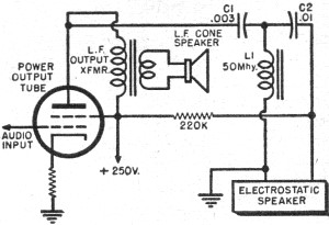
Electrostatic speaker driver circuit.
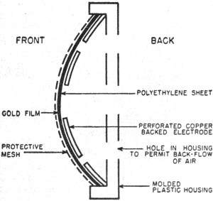
Electrostatic speaker construction. Electrostatic speakers are beginning to find their way into modern, medium-priced high-fidelity equipment. It seems a good idea, then, to review the principles of this unique kind of loudspeaker to see how it fits into the hi-fi picture of today. An electrostatic speaker is nothing more than an elegant capacitor having one flexible and one rigid plate. The principle of its operation is quite simple. Audio voltages applied to the plates of the capacitor set up a varying electric field between them. Since this field contains more or less energy depending upon the amplitude of the potential differences, the flexible plate is caused to move in step with these varying potentials. The air in contact with the moving electrode is then set in motion at an audio rate and sound results. A typical circuit in which an electrostatic speaker is used in combination with a PM cone speaker to form a "woofer-tweeter" arrangement is given in the figure. Capacitors, C1 and C2, and inductance, L1, form a cross-over network which feeds the high frequency audio to the electrostatic speaker while keeping the low frequency components directed toward the low-frequency cone speaker transformer. Early models of electrostatic speakers had two big disadvantages: they could not reproduce the low audio frequencies well and they often suffered voltage breakdowns because of the poor quality of the dielectric materials available at that time. The first problem is avoided by confining operation of the electrostatic speaker to the approximate audio range of 6500 to 15,000 cycles per second. A low frequency speaker is then required, of course, to supplement the capacitor speaker, that is, to provide reproduction over the range of 20 or 30 cycles to 7000 cycles or so. The second problem no longer exists because of the excellence of the new polyvinyls and polyethylenes which can withstand relatively high voltages without puncturing. The illustration shows the construction of one modern type now being installed in several hi-fi "packages." The perforated copper-backed plate serves as one electrode and the gold film sprayed on the insulating foil serves as the other. The polyethylene dielectric carrying the gold film is the flexible electrode and vibrates in accordance with the applied audio voltages to produce the sound. Analog and Digital Signals These rather formidable titles are applied to the two types of electronic computers now in common use. The older of the two with respect to time of development is the analog type. Any information device which accepts data in the form of physical quantities, operates upon the physical quantities, and provides an answer in terms of other quantities according to the rules of its construction may be termed an analog machine. An electrical wattmeter is a perfect example of an analog computer because it extracts from the electricity passing through it information concerning the magnitudes of current and voltage, takes into account the power factor of the circuit, and computes the power consumption in the form of a meter reading which serves as a continuous indication of the circuit wattage regardless of the changes that may be taking place. Its accuracy very obviously depends upon the precision of its design and construction and upon the care taken by the operator in reading it. A slide rule is another perfectly respectable information machine of the analog type: the user translates numbers into movements of the "slip-stick" and transformations from one scale to another, while the slide rule, proceeding according to the rules which have been built into it, provides a product, quotient, square, or cube root with high or low accuracy depending upon the quality of the instrument and the caliber of the operator. A digital machine, on the other hand, works only with numbers. The machine processes the numbers in accordance with the rules of arithmetic and formal logic, and expresses the answer in numerical form. A digital computer could calculate the power consumption in an electrical circuit if it were provided with the numbers corresponding to volts, amperes, and phase angle; then, following the rules implicit in this operation, it would yield the answer in watts with as high an accuracy as the original numbers possessed. The wattage reading, in contrast with the analog watt-meter, would hold only for the instant when the original current and voltage appeared. This is the reason why analog machines are said to operate in "real time" (answers given at the instant when they apply). But it should be noted that the same digital computer which just calculated power consumption may now be used to reckon the income tax of a large business firm without changes in its construction. It is simply fed different numbers upon which the machine will operate with the same high degree of accuracy. Picture a wattmeter being used to figure income tax! Thus, analog computers are built to do a specific, highly specialized job while digital machines can handle any task that can be translated into numbers. Analogs, although having a much lower accuracy potential than digitals, operate in real time and provide continuous answers, even for data that may be constantly in a state of flux. For simple problems, analogs probably never will be replaced by digitals because they are fundamentally simpler in structure and concept, but the digital computer is the machine of the future for solving complex, tedious problems of numerical nature. Power Transformer Quiz Answers 1. 1:2 2. 126 volts 3. 5 amperes - step down 4. 120 volts 5. Since the voltage step-up is 10:1, the primary current is normally ten times greater than the secondary current; when the load on the secondary increases, the primary current increases ten times as fast, causing the primary fuse to blow.
Posted November 1, 2019 "After Class" Topics
|
|||