After Class: Working with Phase-Shift Oscillators
|
|||
There is an old adage that goes thusly: "If you want to build an oscillator, design an amplifier. If you want to build an amplifier, design an oscillator." Its basis is the difficulty that can be experienced in obtaining the right combination of feedback phase and amplitude. Of course experience, use of simulators, and careful circuit construction minimize the opportunity for validating that saying. The basic requirement for an oscillator is feedback from the output to the input that is in-phase and great enough in amplitude to maintain, via the amplifier's gain factor, a constant output level. Tuned L-C (inductor-capacitor) tank circuits are often used as simple frequency-determining elements because of their combined resonance characteristics. Phase shift oscillators are a type of oscillator that can be built without inductors. Instead, they rely on the phase shift of a series of capacitors and resistors to obtain the 180-degree phase shift needed from output to the input to sustain oscillations. Frequency control is not typically as stable as with a tank circuit or a crystal, especially as temperatures change. This type of oscillator definitely feeds the aforementioned adage more so than those with circuits exhibiting high Q factors. This article from Popular Electronics covers some of the fundamentals (pun intended). After Class: Working with Phase-Shift Oscillators
Special Information on Radio, TV, Radar and Nucleonics Most oscillators that utilize resistance-capacitance tuning generate triangular, trapezoidal, or square waves. When one thinks of the generation of sine waves, he usually visualizes an inductance-capacitance tuned type such as the Hartley or Colpitts circuit. There is a class of RC oscillators, however, that is capable of yielding excellently formed sine waves and, because of the absence of coils or transformers, these oscillators are very attractive to the experimenter. Of the three common circuits in the latter group (the Wien bridge, the bridged-T, and the phase-shift oscillator), the phase-shift type is the simplest to build, contains the fewest components, and is very easy to get working.
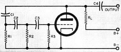
Fig. 1 - Theoretical phase-shift oscillator circuit. See text. Practical circuits are shown in Figs. 2 and 3. Basic Oscillator The fundamental circuit of the phase-shift oscillator is given in Fig. 1. Like all oscillators, action is initiated by some random fluctuation in the tube current or voltage, such as is due to thermal or shot effect. To explain the operation, let us assume that the grid of the triode becomes very slightly positive for an instant. When this happens, the plate current increases slightly, causing the voltage drop across plate-load RL to increase somewhat above its standby value. The extent of this increase depends upon the voltage gain of the tube; the greater the gain, the larger the change in voltage drop across RL. A voltage drop of this nature causes the plate voltage of the tube to go down, thus making the plate negative-going. Since a positive-going grid has caused a negative-going plate, we can say that the "signal" on the plate is out of phase with the signal on the grid by 180 degrees. The plate variation is now fed back to the grid through three RC groups: C1-R1, C2-R2, and C3-R3. Each group can produce a voltage phase shift of its own. Considering only the first group (C1-R1), the voltage appearing across R1 will lead the signal voltage pulse from the plate by an amount determined by the ratio of the capacitive reactance (Xc) of C1 and the resistance (R) of R1. Capacitive reactance depends on frequency as well as on capacitance, so that there must exist some frequency for which the phase shift for C1-R1 will be exactly 60°. Now the voltage that appears across R1 is applied across the C2-R2 group. Assuming equal capacitors and resistors throughout the circuit, then the phase shift across C2-R2 will also be 60° for this special frequency, making a total phase shift of 120°. Finally, a third 60° phase shift across the last group (C3-R3) results in an overall voltage change of 180° from the time the signal leaves the plate to the time it returns to the grid. Adding the normal triode phase change of 180° described above to the C-R phase shift of 180° gives us a total inversion of 360° between the initial voltage fluctuation and the amplified pulse that returns to the grid. This, of course, is exactly what is needed for sustained oscillation - feedback in phase with initial signal, or positive feedback - so that a sine-wave voltage appears between the plate of the triode and B-. This voltage may be taken from the plate through a capacitor (C4) as the oscillator output. Phase-Shift Frequencies. The frequency of the output voltage is automatically "selected" by the oscillator circuit to conform with the required 60° phase shifts just discussed. This means, of course, that control of frequency is obtainable by varying either the resistances or the capacitances. In practice, anyone of the resistors may be a potentiometer to provide a relatively narrow range of control. Frequency variation over a substantially wider range may be realized by varying all three resistors simultaneously; a three-gang potentiometer is ideal for this purpose. The versatility of a well-designed phase-shift oscillator is evident when we consider that it can be constructed for frequencies as low as one cycle per minute and as high as 100,000 cycles per second. Phase-shift oscillators can't be beaten for audio testing, code practice, gain control (as in guitar vibrato amplifiers), or for any other application requiring a stable, reliable, pure sinusoidal output.
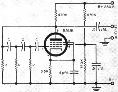
Fig. 2 - Pentode phase-shift oscillator. Capacitors labeled "C" have same value; resistors labeled "R" are equal in resistance. Refer to Fig. 4 for "C" and "R" values for given frequencies.
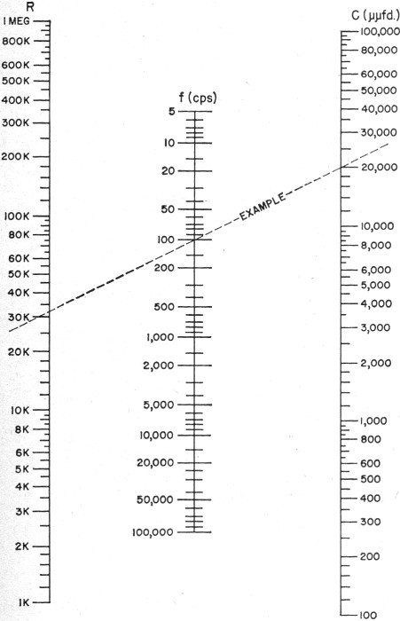
Fig. 3 - Dual-triode phase-shift oscillator. All "C's" are equal and all "R's" are equal. The nomogram will help you choose values for given frequencies. Practical Circuits It can be shown mathematically that a minimum voltage gain of 29 is necessary to provide satisfactory performance at a single frequency. To insure strong oscillation over a range of frequencies, the gain must be somewhat higher than this. Hence, a practical phase-shift oscillator requires either a high-gain pentode or two triodes in cascade for sure-fire operation. An example of a pentode oscillator is shown in Fig. 2, and a dual-triode type is shown in Fig. 3. In the latter circuit, the feedback voltage for sustaining oscillation is taken from the cathode of the second triode. Since there is zero phase shift between the grid input and cathode output voltage of a vacuum tube, the second triode does not introduce any complications when used this way. Instead, it provides a low-impedance source for the feedback voltage and prevents the output load (headphones, speaker, etc.) from causing oscillator instability due to loading effects. The nomogram given in Fig. 4 will provide you with the required R and C values for any frequency between 5 cps and 100,000 cps. Merely select a value for C (all three capacitors are equal), then lay a straight-edge from this value of C through the desired frequency. The intersection of the edge with the R-axis on the nomograph tells you the value of all three phase-shifting resistors. The same procedure is used for finding f if R and C are known, or finding C if R and f are known.
Fig. 4 - Nomogram for obtaining required component values. To determine either "C," "R," or "f" if the other two values are known, lay straightedge to intersect vertical axis at known figures and read unknown figure from the remaining axis.
Posted October 22, 2020 Nomographs / Nomograms Available on RF Cafe: - Parallel Series Resistance Calculator - Transformer Turns Ratio Nomogram - Symmetrical T and H Attenuator Nomograph - Voltage and Power Level Nomograph - Nomogram Construction for Charts with Complicating Factors or Constants - Voltage, Current, Resistance, and Power Nomograph - Resistance and Capacitance Nomograph - Voltage, Power, and Decibel Nomograph - Resistance and Reactance Nomograph - Frequency / Reactance Nomograph "After Class" Topics
|
|||