Room Acoustics for Stereo
|
|
Home entertainment is as big of a deal (or bigger) today as it was in the 1960's and 1970's when high fidelity personal sound gear was coming into the mainstream. Capability and features were going up while the price was coming down on really nice equipment. In order to achieve theater quality sound from your stereo and/or large screen television, thought and planning is essential or you will end up with a confusing mess of directed and reflected sounds. This article, a continuation of "Room Acoustics for Stereo" in the January 1960 issue of Electronics World, contains very valuable information on room configuration and sound absorbing materials and strategies. A fairly extensive table of common floor, wall, and ceiling sound absorption coefficients is provided, as are charts of reverberation times of various venues and volumes. See also "More About Wide-Stage Stereo" in the March 1960 issue of Electronics World. Room Acoustics for Stereo - Part 2: Reverberation & Room Treatment
How the optimum room reverberation is obtained and room resonances are controlled by the use of standard decorative and special acoustic materials. One requirement for a good listening room is that it have the proper reverberation time - or liveliness - to simulate good concert hall conditions. Control of reverberation may be achieved by using standard home decorative materials and commercial sound absorbent tiles. By means of absorption tables covering architectural materials used in home construction, ordinary decorative materials, and commercially available acoustic tiles, it is fairly simple to calculate and "correct" a room to provide proper reverberation conditions.
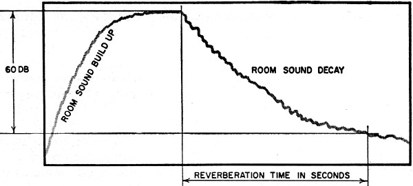
Fig. 7 - When a sound source continues to operate, diffuse reflection builds up until the sound level reaches steady state.
Fig. 8 - Reverberation time is the time, in seconds, taken for steady sound to be reduced to a millionth of its original level Reverberation A room in which sound is to be produced or reproduced, whether live speech and music direct from the piano sounding board or reproduced sound from loudspeakers (monophonic or stereo), must meet certain acoustical conditions if the sound is to be heard properly. A good "listening" room should have correct reverberation properties and generate a minimum of multiple echoes. Analytically, reverberation is a measure of how fast a room will cause sound to be reduced to a certain level after the source of sound has ceased to emit its signal, providing the sound has been fully built up in and has "saturated" the room before the source was stopped. We naively state that reverberation is the quality of "liveness" of a room (to sound) but what is the actual mechanism of room acoustics that leads to reverberation? In Fig, 7 A let the loudspeaker in the corner generate a constant-frequency and constant-amplitude sound. The wavefront emerging from the loudspeaker builds out in a spherical shell of constantly enlarging radius. As soon as that first wavefront reaches a reflecting surface, as at point P1 on wall A-B, the wavefront will be reflected, This reflection travels outward from the wall just as if there were an additional actual sound source at wall A-B. Again the sound from this new source travels out in ever-increasing spherical fronts until it hits another surface like wall D-C from which it will again be reflected as if there were another sound source at P2 on that wall. Thus these reflections will continue until there are a great number of these reflected rays travelling through the room, as shown in Fig. 7B, producing a generally diffused sound condition throughout the room - as long as the source continues to operate. When the source of sound stops, the diffuse reflections do not stop immediately because the sound that has left the speaker has a finite speed of travel. The sound will keep reflecting in a completely random manner, each reflection being successively weaker than the preceding one. The more absorbent the walls, the less sound power gets reflected and the quicker the sound dies out. When the sound dies out slowly, there is little absorption within the room, and the room would be termed "highly reverberant." Reverberation, then, is correlated with time - how fast does the sound die out? This is a measure of reverberation-"time." Consequently, "reverberation time" has been defined as the time (in seconds) that a steady-state sound in a room decreases to 1-millionth (1/1,000,000) of its original intensity (after the source has stopped). See Fig. 8. In easier terms, when the intensity of the sound, after the source has stopped, decreases by 60 db, the time it took to drop to this level is the reverberation time. Now, just what sort of reverberation time period should one expect of a listening room, especially one intended for stereo listening? In Part 1 of this series we noted that perhaps a shorter reverberation time for stereo might be desirable since the very essence of stereo itself "psycho-enlarges" the room. This question of optimum reverberation time cannot be answered by complete specifications down to the last decimal place. It is a variable, depending on room or auditorium size and the type of program material being presented. Studies have shown that while an auditorium sounds right - has an accepted reverberation time - for a full symphony orchestra, it may not have the proper reverberation for chamber music or voice.
Fig. 9 - Optimum reverberation times.
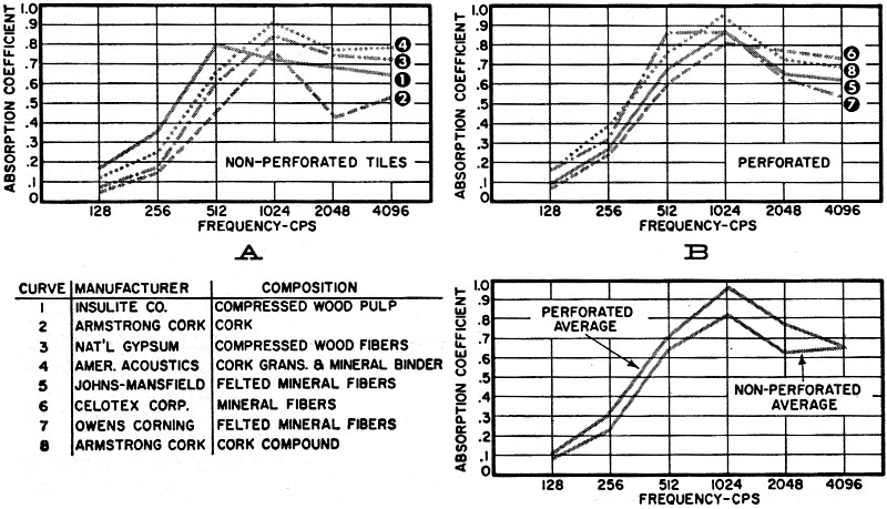
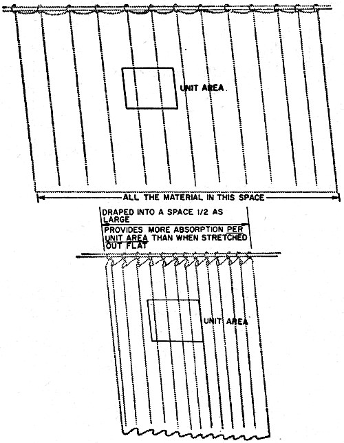
Fig. 10 - Average absorption characteristics of representative acoustic tiles. Many studies have been made of music rooms, auditoriums, concert halls, churches, and similar structures to determine the acceptable range of reverberation times and these figures have been generalized in Fig. 9. While it would be nice to have an instrument at home which would enable us to check the reverberation time of our listening room against this sort of chart, such equipment is quite expensive (for home use) and requires an experienced professional hand at the controls. For such non-critical conditions in the home it is possible to calculate the reverberation time of any room by measuring its physical size and applying information from the charts and tables to - be discussed shortly. In very simple form, T = 0.05V/A, where T is the reverberation time of the room (in seconds), V is the volume of the room (in cubic feet), and A is the total absorption of the room and its contents. V, the volume of the room, is no trouble to calculate. Total absorption may be judiciously estimated by reference to established tables which give the absorption coefficients of various materials used in the construction and decoration of the room. For purposes of this article, we must, of necessity, limit ourselves in listing absorption coefficients. What we will do is list the more common household materials which may affect the acoustic conditions of our listening room and then work with these. Table 1 itemizes such common household materials while Fig. 10 illustrates, in chart form, the absorption characteristics, as a function of frequency, of some representative commercial materials available for acoustical correction purposes. It will be observed that, in general, the softer the material, the more it soaks up the sound. Another interesting item to be observed from Table 1 is that a given material can be arranged so that its absorption characteristic may be varied. Velours, for example, when hung flat, have much less absorption per unit area, as shown in Fig. 11 than, if we drape or "bunch" a length of velour into an area one-half its flat length. As Table 1 indicates, we practically double the absorption. This, then, is a basic principle by which highly absorbent surfaces are obtained ... "amplify" a given absorptive area by providing a dimension in depth for more absorption. Acoustical Tiles Most of us are familiar with those off-white squares of "sound absorbent" material widely used on the ceilings of public buildings. Such materials are known as "tiles" in the trade. Fig. 13 shows some typical units of this type. The tiles are generally a foot square and may be obtained in several thicknesses - 3/4," being standard for home use. The tiles are made in a variety of materials and textures. Some are simply rough surfaces with "cracks" or fissures apparent on the surface while others are of the perforated variety, some with evenly spaced holes and some with randomly spaced perforations. Although an inspection of Fig. 10 indicates that the absorption characteristics of these materials are roughly similar, the perforated variety has some advantages in absolute absorption, especially in the mid-frequency range, although the "curve" of absorption is not as smooth as for the unperforated type.
Fig. 11 - Here is a simple method of changing the amount of absorption in a typical listening room, as required. If such acoustic tile is to be applied for the purposes of reducing noise due to the human voice alone, as in restaurants and offices, then the perforated material, with its accentuated mid-frequency absorption (where most of the voice frequencies are found) is perhaps most suitable since the ear is especially sensitive in this area. If, however, we wish to absorb a fuller range of sound than that of the human voice, then the fissured material is preferable because of the smoother absorptive curve, although more of the material may be required. Moreover, as far as the home is concerned, the fissured or sculptured material will fit in with the decor better and look less "industrial" than the perforated variety. It is interesting to note that the rise in the absorption curve of these materials roughly coincides with the frequency range where the stereo differentiating effect takes place. In the region above 300 cps, spatial differentiation becomes effective and separate speakers reproducing these frequencies are necessary for proper spatial perspective. Thus the effectiveness of these sound absorbing materials roughly matches the frequency range where the stereo effect becomes discernible - making them eminently suited for acoustic adjustments and compensation for stereo reproduction. Determining Reverberation To illustrate the application of the reverberation formulas in conjunction with the tables, let's choose a room with the typical dimensions shown in Fig. 12. In its bare, untenanted state, the room consists of a pine floor with the walls and ceiling of plaster, lime, and sand finish on metal lathing. The windows, of course, are of standard glass. We know intuitively how a loudspeaker would sound in this bare room, but just as a simple exercise to illustrate the use of our "mathematical tools," let us put down some numbers that will provide the figure of (de) merit for this room.
Fig. 12 - This completely bare hard room will be too "live", while the room will be too "dead" if completely padded. Figures used are shown below. We are going to apply the reverberation formula (T = 0.05V/A) previously discussed, which relates room volume to total absorption. To get total absorption, we simply add up all the absorption units of all the surfaces of the room by multiplying the areas of the various exposed surfaces by their respective absorption coefficients. In simple cases such as this, the absorption coefficient for 512 cps is used. Thus, as indicated in Fig. 12, the floor has an area of 25' x 20' or 500 square feet. It is made of pine flooring which has an absorption coefficient of 0.09 (per square foot). Its total absorption is 500 x 0.09 or 45 units. The "units" for the walls, ceiling, and windows are figured in the same way on the basis of their areas and absorption coefficients. The absorption of the room totals 128 units and, as indicated in Fig. 12, the reverberation time becomes 1.95 seconds. Checking back to Fig. 9 we find that this reverberation time is far too long for proper definition of sound in a room this size (5000 cubic feet). The room will be too "live" which, of course, we knew from the start. Now let's go to the other extreme and drape all the walls (using a drape which has an absorption coefficient of 0.55) and lay carpeting on the floor. The second tabulation, Fig. 12, shows that the total absorption will now be 710 units. Again applying our reverberation formula we get 0.35 second, which we can see from Fig. 9 is far too low - much too dead - which we also probably surmised from the excessive padding added to the room. Somewhere between the completely live room (128 units) and the over-subdued room (710 units), there must be a happy medium. Without going through the calculations, but following the same general method, we find that if we drape only one-fifth of the area of each wall and carpet the floor we arrive at a total absorption of 357 units (per the third calculation of Fig. 12). This room, now re-adjusted to 357 units, yields a reverberation time of 0.70 second. Although this figure is a little on the low side, it will insure a reasonable acoustic "liveness." The room should actually be a bit more on the live side because if you put a couple of upholstered settees in the room (at an absorption figure of 5 units each) and sprinkle generously with seven or eight human beings (4 absorption units each), the total absorption will be gradually increased to approximately 400 units which will tend to pull down the reverberation properties of the room to near the lower "acceptable" limit.
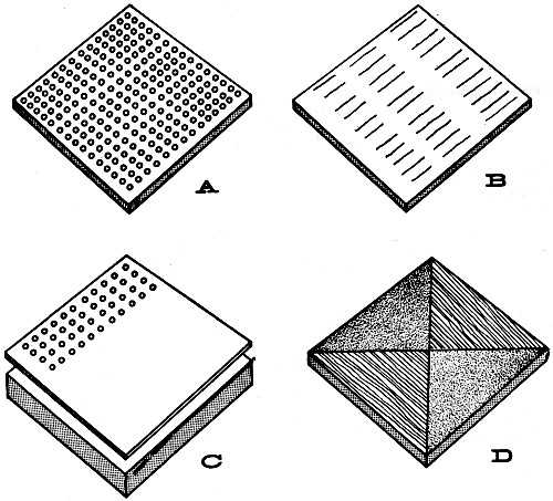
Fig. 13 - Commercial acoustic tiles. (A) Soft fibers pressed into rigid, but acoustically soft mass with perforations to absorbent body; also with surface absorption. (B) Soft fibers pressed into rigid, but acoustically soft mass with surface cracked, or fissured, for added absorption. (C) Hard panel, such as Masonite, perforated and backed by thickness of absorbent material; no absorption by surface . (D) Same as (B) but with surface sculptured for decorative effect. Altering the Room As just demonstrated, much can be accomplished in the line of altering the reverberation of a room by judicious application of various household materials, especially those in the drapery category. Thus, for instance, if one were to hang draw drapes across the four walls of a room (of the dimensions of the one given in Fig. 12) and kept the floor linoleum-covered, as in a playroom, the room could measure from 2.5 seconds with the drapes completely retracted to 0.46 second with the drapes fully extended to cover the walls. With this type of arrangement, it would be fairly simple for the host to adjust his room to match the number of guests: For a lot of people - open the drapes and expose the walls; for an intimate soiree - draw the drapes. On the basis that each adult is equivalent to 4 absorption units, one could "calibrate" the drapery drawstring in units of number of guests. We may, of course, use materials which have been developed specifically for sound control, such as the acoustic tiles discussed previously. With these tiles we may control the room acoustics more accurately and with smaller areas of material than with conventional drapes, although combinations of tiles and drapes are practical. Tiles are especially useful when the room decor will suffer from an overabundance of drapery. Actually, the acoustic tiles may be quite decorative as well as functional and lend a clean, uncluttered look to the room. With the modern trend toward "airy" interiors, acoustic tile may actually prove a boon in maintaining this feeling while controlling room acoustics. Many such tiles (especially the perforated ones) can be painted to create interesting decorative effects. One of the most important features of these tiles is that they enable us to treat ceilings as well as walls. Since the ceiling of a room comprises approximately one-sixth of the room's interior surface, it represents a good sized area which cannot be treated other than with tiles. The ceiling cited in our example, 25 feet x 20 feet with an absorption coefficient of 0.06 when bare has only 30 absorption units but when covered with fissured acoustic tiles its absorption becomes 375 units - more than enough to take care of the whole room without treating the other areas. Undesirable Resonances
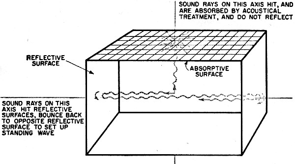
Fig. 14 - Absorbent material on one surface will inhibit a resonance condition between that surface and the opposite one, but will not prevent resonance from being set up between the other room surfaces. Although this method of adjusting room acoustics in one grand stroke is fine for general noise abatement, it is not the best approach to the problem of musical acoustics control. The reason for this is that there may be room resonances set up between the sets of untreated parallel walls which can produce quite disturbing effects to musical sounds reproduced within the room. Room resonances may occur when the dimensions of the room are close to the wavelength of the sound propagated in the room and are most prevalent in the low-frequency region. When the air within the listening room is energized by a sound source, the volume of air enclosed by the walls, ceiling, and floor may be driven into resonance at frequencies which coincide with the wavelength or half wavelength separation of the walls. The very worst shape for a room, acoustically speaking, is a perfect cube because all axes are of equal length and the room is highly excitable acoustically and energetically resonant in all directions at the wavelength (and harmonics of it) which is equivalent to the spacing of the walls. In general, no room dimension should be close to a whole number ratio of another dimension. For normal living rooms, you may consider that if the dimensions of your room are in the ratio of 1:1.25:1.58 then your listening room will be reasonably immune to resonances between the three mutually perpendicular axes. Although there is usually nothing we can do to the dimensions of our rooms, the statement of the condition, as given, is important in that it allows us to allocate our sound absorbent material intelligently. For instance. if there should be a strong resonant condition between two highly reflecting walls, then even large amounts of sound absorbing materials on the floor or ceiling will not affect that particular wall-to-wall resonance to any great extent. See Fig. 14. Thus the technique of treating the ceiling only is not the answer to adjusting the room for music purposes. We must distribute the "treatment" in random fashion to include all surfaces in order to minimize reflections along all three axes. If we thus distribute the treatment throughout the room, not only will we minimize room resonance but we will improve and equalize the general sound diffusion throughout the room - a condition of considerable importance for stereo. Speaker & Listener Locations
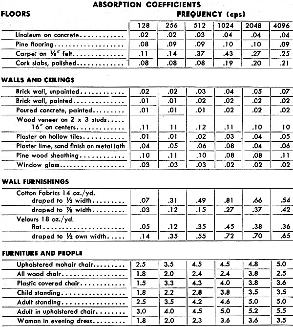
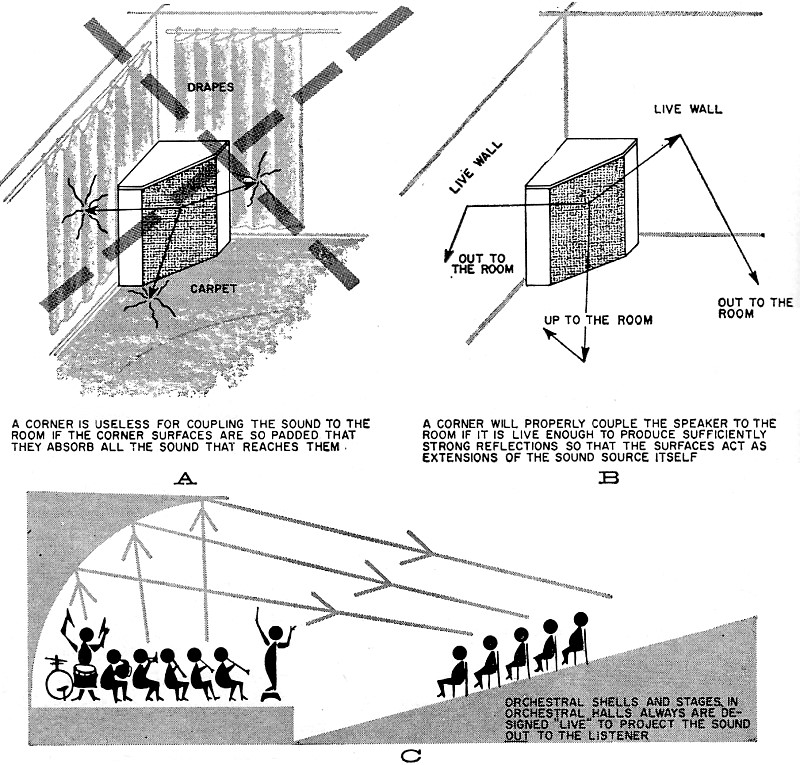
Table 1 - Absorption coefficients per square foot of some common materials are shown. One of the prime considerations in setting up a room for music reproduction - live or recorded - is that the sound source be located in a relatively "live" area so that the sound may be projected into the room. For monophonic applications, an undraped corner of the room is perhaps the best "projector" area of the room. Many articles have recommended locating the loudspeaker in a corner so that the corner can act as a three-sided horn feeding the room. Too little mention is made, however, concerning the acoustic condition of the walls and floors of these "desirable" corners. If the walls and floors are heavily draped and carpeted, as shown in Fig. 15A, the corner would be of very little use. The need for a live backing area behind the sound (Fig. 15B) is dictated by the need for throwing the sound forward - just as is done by an orchestral shell (Fig. 15C). Therefore, absorption techniques that are to be applied should be in the general listening area, with a minimum in the sound generating area. Putting the absorbent material in the listening area serves to reduce unduly strident echoes from live surfaces (removed from the original source) which by reflectively interfering with the direct sound will cause confusion at the listener's ear. In this connection we must also realize that the closer one sits to the source of the sound, the less effective are the surroundings. This effect is especially noticeable in very live rooms. If one were seated close to a hard plaster wall and the sound source is 20 feet away, there would be considerable interference introduced by reflections off the wall. On the other hand, if the walls were heavily draped then the ear would receive very little reflected sound and its major acoustic stimulus would be direct sound from the speaker. We must, therefore, strive for a balance between direct and reflected sound so that while we hear the performance in front of us, we get some general diffuse sound from around us to "liven" the performance. Summary of Principles
Fig. 15 - Speaker placement should be such as to provide proper "live" coupling. Summarizing the various principles outlined for any good listening room - whether for live music, reproduced monophonic or stereo, we have: A. The room should have an absorption characteristic which will provide a reverberation time of from 0.75 to 1.25 seconds. B. The sound absorption material used to achieve this reverberation figure should be distributed throughout the room rather than be concentrated in one area. C. Large, hard parallel reflecting areas should be avoided as they lead to multiple reflections and resonances. D. The sound source should be located in a comparatively "live" area of the room. E. The listener location should not be adjacent to either a hard reflective surface or a totally absorptive surface since in neither case will the listener receive the proper proportion of reflected-to-direct sound in keeping with accepted reverberation practice.
(To be continued)
Posted July 2, 2018 |
|