LC Filters
|
|
Inductor-capacitor (LC) series and parallel combinations comprised the first lumped element electrical filters for frequency discrimination. Below a few megahertz, with a little judicial placement of components and treatment of lead lengths, building a successful LC filter is not hard, and the measured response physical result looks very much like the predicted response - provided the circuit model is sufficiently accurate. Above 50 MHz or so, very careful attention must be paid to parasitic elements (inter-turn capacitance, lead inductance, cross-coupling) to get a good response. The advent of surface mount components has made higher frequency LC filter implementation easier, but at some point above couple hundred MHz lumped components just won't do the job, requiring a switch to resonant cavities, distributed element substrates, and waveguide. Mixed within those purely electrical filter types are electromechanical formats like crystal, ceramic, surface acoustic wave (SAW), bulk acoustic wave (BAW), and others. LC Filters
The author received his BSEE in 1960 and has done graduate work at the Polytechnic Institute of Brooklyn. He joined the company in 1965 as head of the filter design department. Since then he has written numerous digital computer programs on LC filter design and analysis and is doing research on new types of LC filters. He is a member of IEEE, the Professional Group on Circuit Theory. By Stephen Rosenfield / Senior Engineer, ESC Electronics Corp. Are LC filters sophisticated enough to fulfill the needs of today's complex systems? Yes, but you need a specialist who knows filters and a computer which designs intricate LC networks quickly and inexpensively for the job. Take an inductor and add a capacitor; tie them together and you have a system which can store power and filter out noise. LC networks, which incidentally should be called RLC filters since all passive electrical components contain resistance, are first cousins to RC filters which most engineers at one time or another have designed with traditional resistors and capacitors. As a matter of fact, RC filters are fairly well standardized - their design formulas are found in many textbooks. LC networks are by comparison difficult, and a more sophisticated approach is needed. To some degree, the difficulty in LC filter design is directly due to the inductor's design which is in itself an art. For any particular frequency at which a specific inductance value is specified, there are literally hundreds of possible inductors which could be used in the application. In reality, there are only a few optimum choices. One more thing about LC filter design. There are many textbooks and magazine articles which purport to give design information. However, engineers or technicians who require filters should be advised not to design their own networks. An engineer who designs his own LC filter usually finds that he could have specified his requirements to a filter specialist and paid much less for a lot more. The Art of LC Filter Design
Table 1 - Rise times and overshoots of typical filter types. All kinds of filters, such as crystal, mechanical, and ceramic (which we can refer to as secondary types), have evolved from the primary LC type. Designers of these secondary filters always make use of LC filter analysis to help explain the operation of their networks. For most parameters in the secondary filter system, there exists an analog which relates to either an inductance (self or mutual) or a capacitance in the primary LC filter system. As a matter of fact, if this were not true, little could be done in the way of analyzing these types of filters mathematically. Perhaps the degree to which LC filters can be analyzed mathematically explains the degree to which the filters have grown in sophistication. In no other type of filter can the specialist control so many parameters. For example, we are able to provide LC filters with a group-delay constancy of 1% in the passband coupled with an ability to provide extreme selectivity. We can design LC networks which will shape a given signal and stabilize the response to within a few tenths of a dB over an extremely wide temperature and input voltage range. Each year new LC filter capabilities are realized and the end is not in sight. LC filter design has become so sophisticated and competitive that filter designs must be carefully analyzed by digital computers. The digital computer is a necessity, not a luxury. Some filter manufacturers have devised computer programs which will: (1) design a complete filter network from customer specifications, (2) analyze a completed design - tells the engineer whether or not the filter meets all specifications and whether or not it operates efficiently at the extremes of the component tolerances, and (3) optimize an initial filter design. Here the computer picks the best L and C values in a particular branch of a network, giving the filter design engineer a truly optimal network for a given number of inductors and capacitors. The time required - from specification of the filter to delivery to the customer - has been greatly reduced by computer processing. Many filter manufacturers are able to give cost quotations within 24 hours after receipt of the specifications. Design work is so rapid that often filter deliveries can be made in a few days or at most a few weeks. In the past, it often took months, or perhaps even longer for an engineer to receive the required filter.
Fig. 1 - Attenuation and group-delay characteristics of the (A) Butterworth, (B) 0.5-dB Chebychev, and (C) Bessel filter systems. In the past, most filter companies offered catalogues or brochures showing the many filters kept in stock. For example, many types of LC filters such as telegraph and tone-channel networks have been standardized by the electronics industry, that is, these units have fixed bandwidth, attenuation, and input and output impedances. Low-pass filters with particular cut-off frequencies and given impedance levels were also stocked by some manufacturers. Some companies continue to stock these items but, based upon the author's experience, the need for the off-the-shelf unit has greatly diminished. For example, if the engineer thinks he saves money by buying all off-the-shelf item, he should consider his decision carefully. Despite the growth of active filters, which in years past have threatened to "push LC filters out of existence," LC filters have grown in direct proportion to the expansion of the entire electronics industry. But, more and more sophisticated engineers and technicians realize that filters should be designed by specialists. LC Filter Characteristics The LC filter user should know something of the characteristics of various types of units so that he may know if it is feasible to get a filter that meets his needs. We will concentrate on the specific shape of the filter's characteristic, including parameters like group delay, amplitude response in the passband, out of the passband (or stopband) , and in the transitional area between. We will also summarize the transient response of several families of LC filters. Essentially, the several families of filter characteristics can be grouped and represented by a low-pass network. Bandpass, high-pass, and band-reject designs are related to the low-pass case by simple frequency transformations. Within the general characteristics of each family, the rate of attenuation outside the passband is set by the number of poles (directly related to the number of inductors and capacitors within the filter). Fig. 1 shows the amplitude and group-delay characteristics of Butterworth, Chebyshev, and Bessel filters while Table 1 summarizes their respective rise times and over-shoot.
Fig. 2 - Typical questionnaire designed to aid the filter specialist in devising the right filter for the customer's needs. Butterworth filters are derived on the assumption that behavior at zero frequency is far more important than behavior at any other frequency. In this way they are similar to the classical image-parameter filters. As a matter of fact, a three-pole Butterworth filter is identical to a three-pole image-parameter type. This d.c. approximation leads to a class of filters with good phase response and good amplitude response but poor characteristics around the cut-off frequency (the 3-dB point). The Butterworth function is unsuitable for applications that require transmission of frequencies in the passband and sharp rise at cut-off. As Table 1 shows, overshoot increases with the number of poles in the Butterworth filter. Chebyshev filters are derived on the assumption that all frequencies in the passband are of equal importance. The Chebyshev function is useful in applications where the amplitude is of primary concern. This family gives a more constant attenuation in the passband than the Butterworth type and gives much greater attenuation in the stopband. Unfortunately, Chebyshev filters offer little improvement in decreasing the size of overshoot. Bessel, also known as Thompson filters, achieve their excellent phase linearity at the expense of the slow rate at which signal amplitude decreases in the stopband. They can pass rectangular pulses with little overshoot (Table 1), negligible over-all distortion of shape, and the time delay is almost constant with frequency for passband signals. They are well suited to pulse-modulation systems and applications where minimum deterioration in pulse transmission is required. Some other filter types, not illustrated here, attempt to combine the characteristics in which each of the three already described filter types excels. The Transitional Butterworth-Thompson (TBT) is well defined by its name. It is used where somewhat greater attenuation is needed than that which the Bessel offers, and somewhat more overshoot can be tolerated than that which the Butterworth allows. Optimum-L filters combine good selectivity with a uniformly changing phase characteristic. There is less attenuation than in the Chebyshev filter but also less time delay over a greater bandwidth, therefore better transient response. They are useful in phase-angle modulated systems. Where amplitude is of prime importance and stopband and passband ripple are allowable, the most efficient type of filter characteristic is the relatively new elliptic type. For any given number of poles, these filters provide the most efficient amplitude vs frequency characteristics of any type. Unfortunately, their group-delay and overshoot characteristics are poor and difficult to predict. See Fig. 3. Fig. 4 shows the network configuration for Butterworth, Chebyshev, and Bessel filters. Fig. 5 is an elliptic filter schematic. The "Interface" Problem
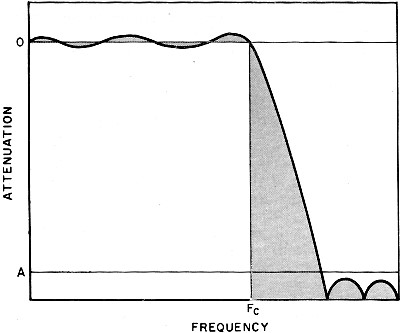
Fig. 3 - Elliptic filter characteristic attenuation showing occurrence of ripples in the passband and stopband. For an efficient filter to be designed, there must be honest and knowledgeable communications between the requesting engineer or technician and the filter designer. First, the engineer must know why he wants a filter. He must know the waveforms in his system, what he wishes to change, and what characteristics he wishes preserved, and he must know what frequencies must be eliminated. Therefore, the engineer must analyze his waveform and know why it is the way it is. Even if the filter designer knows something of the system's function, he is really an expert only within his own domain, and hence must be presented with information on circuit conditions. At an early point in the specification of the filter, the engineer must decide what type of filter he needs. Does he need an LC, mechanical, or crystal filter? To aid the engineer in his choice, a chart of frequency vs percentage bandwidth ranges is shown on page 44 of this section. (Note these are approximate and should serve only as a casual guide. Certain filter manufacturers may take issue with these limits.) Assuming that the specifying engineer knows the composition of his waveform and what changes he wants the filter to make, he now should specify a filter with the minimum requirements that meet his objectives. Overspecifying or underspecifying a filter may ultimately lead to an impractical design or a costly or time-consuming mistake. Based on our company's experience in designing LC filters, it is quite obvious that the specifying engineer tends to overspecify selectivity while overlooking other parameters that may be critical to his needs. To alleviate some of these problems, some suppliers have prepared detailed questionnaires which the filter user completes and returns to the designer. Very careful thought has gone into the preparation of these forms and we will go over a typical questionnaire item by item (see Fig. 2) to help clarify the "interface" problem - the communication between user and supplier. 1. Filter Type: Here the word "type" refers to low-pass, high-pass, bandpass, or band-reject. It should be obvious to the filter user the type he requires. If his signal is d.c. or some frequency which will suffer from harmonic interference, he needs a low-pass filter. If his information is in a restricted band above d.c. and signals are interfering on both sides of the band, he needs a bandpass type, Where a network has a limited band of signals to be eliminated (above d.c.) , the user may require a band-reject network. A subharmonic problem is generally taken care of through the specification of a high-pass filter.
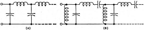
Fig. 4 - General network configurations. (A) low-pass and (B) bandpass for Butterworth, Chebychev, Bessel filters. We have simplified the explanation of the differences among filter types, but, in addition to these "simple" cases, there exists a myriad of other applications. For example, filters may be used to separate signals into discrete bands of frequencies so that information can be sent efficiently through transmitters which have limited bandwidths (see Fig. 6). Upon reaching a receiver, the separate signals are recombined to produce the intelligence. A group of bandpass filters composed of contiguous frequency passbands are connected with inputs in parallel. The information is separated into frequency-limited bands and sent to different outputs. A similar group of filters on the receiving end, with outputs in parallel, will combine the separate bands and restore the signal to its original information capacity. Here the user must supply the filter designer with specifications for each group of bandpass filters which work together to accomplish the required function. Many other functions, too numerous to be covered here, can of course be accomplished through the use of low-pass, high-pass, bandpass, and band-reject type filters. After the decision as to "type" has been made, the amount of selectivity needed must be expressed quantitatively as in Item 1a in Fig. 2. This is generally done in terms of the maximum dB of attenuation allowable within the passing region or passband, and a minimum amount of loss needed in the attenuating region of stopband. Here, again, we stress the need for an honest evaluation on the part of the user of his requirements. This enables the filter to be manufactured in the most efficient and economical configuration. A simple example of overspecification of selectivity follows: Suppose an engineer wishes to suppress the seventh and higher harmonics of a 1-kHz. square wave in order to slow down the waveform's rise time. The filter specifier may decide arbitrarily that if the 7-kHz and higher components of the signal are attenuated 60 dB, his problems are solved. He fills out Item 1 of the questionnaire as follows: (a) Fr reference frequency 1-kHz insertion loss 1 dB max. F1 5-kHz attenuation 3 dB max. (He wishes to pass frequencies up to harmonic five, allowing a 3-dB maximum loss at 5 kHz.) F2 7-kHz, 60 dB minimum. (b) - Maximum passband ripple ±1 dB. This looks simple enough, but let's examine this more closely.
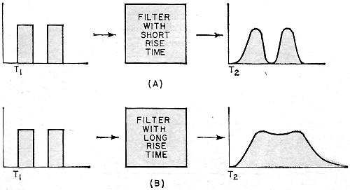
Fig. 5 - (A) Low-pass and (B) bandpass elliptic filter circuits. If the user remembers that the Fourier series shows harmonic number seven of the square wave is already 1/7th of the first harmonic, or 17 dB below the 1-kHz fundamental, he really needs 60-17 or 43 dB attenuation to produce the required result. A filter which produces 60-dB attenuation at 7 kHz (with 17-dB attenuation wasted) costs more to produce than a filter with the acceptable attenuation of 43 dB. On the other hand, there may be more subtle problems in deciding the amount of attenuation allowed in the passband. It is easy to say "let harmonic number five (5 kHz) come through the filter with no more than 3-dB attenuation," it is more difficult to explain why. 2. Impedance: This information seems obvious. The user, after deciding where the filter is to be used, notes the input and output impedance (Zsource and Zload, respectively). The problem here is that the circuit impedance could vary with frequency. Most filters will cause distortion if the input and output impedances are not constant. If the filter design engineer is informed of this impedance variation he might be able to design around it. In this way, some circuit troubles may be avoided when the filter is inserted into the system. Too high or too low a design impedance can make filter design unrealistic. A filter that must operate at 10 MHz at an impedance of 100,000 ohms may possess 1-millihenry inductors and 1-picofarad capacitors, a poor combination. Perhaps the filtering should be done in another part of the circuit where impedance values are more compatible. 3. Phase and Transient Characteristics: Filter specifiers seem to be more ignorant of phase shift and time-delay requirements than of any other parameter. In the past, where amplitude modulation was the primary method of information transmission, it was not important for the engineer to be concerned about phase and time delay. Now the complexity of modern signals through the newer modes of signal processing, such as frequency, pulse, and continuous-wave modulation, forces the well-informed engineer to reckon with these variables. Suppose we are dealing with a pulse transmission system where the requirement is that the output pulses have the same shape and separation as the input pubes except for a time delay T = T2 - T1 as shown in Fig. 7 A. It is clear that a filter with a long rise time is not suitable because the pulses would "smear" over each other, as seen in Fig. 7B. The same can be said for long settling times. Obviously, the best filter for the pulse transmission system is a constant-delay filter with small rise and settling times.
Fig. 6 - Contiguous bandpass filters separate, combine signals.
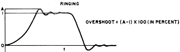
Fig. 7 - In most pulse transmission systems, short rise time filters are better (A). Long rise time filters smear the pulses (B). Engineers working with pulses may appreciate the term "overshoot" more than certain other engineering types. In color-TV transmission, too much overshoot causes the TV picture to have an excessive mount of blue haze, not the most satisfying color for human skin tones. Fig. 8 defines overshoot. A word of caution should be given here. The author has stressed the significance of understanding phase shift and time delay, and has given examples of their effect on the user's system. If, however, special phase-shift or transient characteristics are not needed. it would be unwise for the filter user to specify them. Their specification will ultimately require a more costly filter. 4. Voltage Level: Linear networks of which LC filters are a part, generally remain stable with voltage and power. But any linear network will saturate when loaded by too high a signal. It is especially important for the filter designer to be aware of the incoming voltage swing when specifying low-frequency filters below 5 kHz. At low frequencies, inductors tend to saturate more than at higher frequencies due to increased hysteresis losses. High dynamic ranges of voltage may be critical if the filter has been specified to have a high degree of stability. The filter specialist has at his disposal, components such as thermistors and varactors which are able to compensate for input variations. But he can only compensate, when the user informs him of the system's conditions. 5. Temperature Range: All capacitors and inductors vary (in value) over a temperature range. Ambient temperature and the range of temperature variations are frequently inadequately specified. A probable reason is that although users are aware of the temperature problem, they care little about it, and shift the responsibility to the component supplier. Often, a filter user will arbitrarily enter the operating temperatures as -55° C to +125° C thereby covering himself for any error he may have made in predicting the actual range. The restrictions now placed upon the filter supplier are numerous. He cannot use certain types of capacitors such as polystyrene and ceramic, he must eliminate certain encapsulating compounds, and he must completely stop the use of certain inductive devices such as ferrite pot-cores with small air gaps. All this is the consequences of a wide temperature range. With all these restrictions, the filter specifier must now pay a price for the extra design time and more costly components which require temperature compensation. A filter specialist is able to compensate for temperature changes easily, but why compensate when it really isn't necessary. 6. Application: This part of the questionnaire is an aid to the user who is not exactly sure his specifications are correct. Sometimes this added data helps the designer understand the user's needs. Mechanical specifications, Items 7 through 10, are obvious and require no comment. What's Ahead
Fig. 8 - How to calculate the degree of overshoot. Through the use of the digital computer, new families of LC filters have been built that have never previously been thought possible. Now, the computer is the top tool of the filter design engineer. Through computer usage, the price of LC filters has been slashed. Prototyping costs have also dropped substantially in recent years and appear to have a tendency to continue doing so. Innovation and experimentation are not expensive any more and the filter designer does not have to build the physical filter to prove his design. A mathematical model of the filter is, instead, analyzed by the computer, and only after careful study, with many alternate designs weighed, is the filter released to the shop for construction. The actual computer time has not been days or weeks, but seconds to minutes. LC filters, which cover the widest of frequency ranges have been used in more networks than any other type of filter. In all probability, these filters will continue to increase in range. This is in part due to the new components such as ceramic chip capacitors, which cut package sizes, and new inductive devices.
Posted January 25, 2018 |
|