Crystal Filters
|
|
As with most technologies that have been around for decades, the fundamentals of crystal filters have not changed with time. Materials and methods have changed, of course, but the equivalent lumped element model (using resistors, capacitors and inductors) of a crystal filter is essentially the same today as it was in 1969 when this article appeared in Electronics World magazine. Open a first semester electronics circuits textbook and the chapter on crystals will look much like this piece by Mr. Robert Kent, of Damon Engineering. The use of crystal had a profound impact on filter design because their extremely high "Q" factors permitted very sharp band edges for rejecting nearby unwanted signals. Relatively low power handling and high insertion loss prevents them from being used in receiver front ends requiring high sensitivity, but they work miracles in IF (intermediate frequency) and baseband circuits after a stage or two of signal amplification has occurred. Crystal Filters
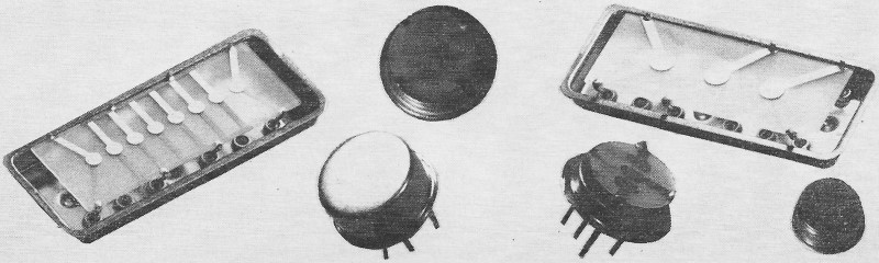
The author received his B.S. from Moore School of Electrical Engineering, University of Pennsylvania, in 1950 and his M.S. in electrical engineering from MIT in 1952. From 1952 to 1960, he was a staff member of MIT's Research Laboratory of Electronics, participating in the development of missile guidance and electronically scanned radar systems and in the design of a satellite gravitational red-shift experiment. He has been with Damon since 1961 where he has been active in the design of quartz crystal devices. He was named to his present post in 1968 and is now engaged in the development of monolithic piezoelectric devices. He is a member of IEEE, Eta Kappa Nu, Sigma Tau, Tau Beta Pi, and is an associate of Sigma Xi. He holds a patent in the area of phased arrays employed for missile guidance. By Robert L. Kent / Engineering Manager, Electronics Division, Damon Engineering, Inc. Like other electronic components, crystal filters shrank physically when performance and reliability improved. They offer users the maximum in stability and selectivity; are favored in military, commercial applications.
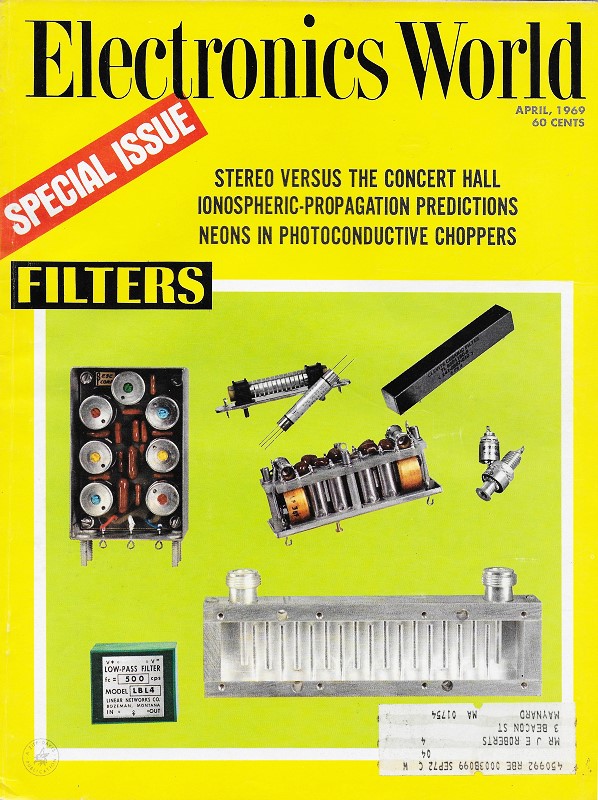
Fig. 1. The equivalent circuit of a 10-MHz quartz crystal.
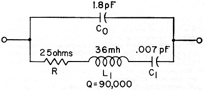
Fig. 2. The unbalanced half-lattice uses two crystals and is building block for more complex filter configurations. In the beginning, crystal filters could only be used in equipment where size and weight were of little consequence. After World War II, weight and volume went down while performance and reliability went up an order of magnitude. Now there is a monolithic crystal filter which again cuts size and costs, has greater reliability, and better temperature stability. Crystal filters are used wherever the bandwidth occupied by a desired signal is no more than a few percent, preferably no more than a few tenths of one percent, of the operating frequency. Extremely narrow bandwidths are attainable because of the inherent high "Q" of the quartz resonator. A "Q" of 100,000 is as readily obtainable with a quartz crystal at 10 MHz as a "Q" of 100 with an LC resonant circuit. High-frequency crystal filters have made a major impact on h.f. narrow-band communications. System performance characteristics have been improved and complexity reduced through the use of single-conversion receiver designs employing crystal filters. A more recent application is in the area of frequency synthesis, where crystal filters are used to clean out spurious signals caused by mixing and other non-linear synthesis operations. What Users Should Know Before discussing "why" and "how" an engineer should select and use a crystal filter, it is worthwhile to examine very briefly some filter designs. As previously stated, crystal filters are narrow-band devices. They are used to select, or reject, a very narrow frequency band out of a broad spectrum. Quartz crystals provide the required selectivity when used in resonant circuits in conjunction with capacitors and inductors. The most common equivalent electrical circuit of a quartz crystal is shown in Fig. 1. Shunt capacitance, C0, limits the bandwidth. Similarly, the series resistance, R, along with temperature stability, places a lower limit on practical bandwidths. To obtain a symmetrical attenuation characteristic in a crystal filter, the shunt capacitance of the crystals is often "balanced out" by means of bridge networks. The unbalanced half-lattice (Fig. 2) is commonly employed for this purpose, and becomes the building block with which more complex crystal filters are assembled.
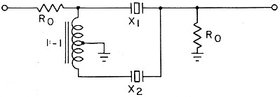
Fig. 3 - A single hybrid transformer can be used to serve two filter sections in this circuit. A six-crystal filter is shown in Fig. 3. Note that a single "hybrid" transformer can serve two of the filter sections. The number of crystals which the filter uses is usually determined by 'the "shape factor," i.e., the required selectivity. The shape factor is a ratio of bandwidths measured at two different attenuation levels, such as -60 dB and -3 dB. The shape factors for Butterworth (maximally flat) filter designs are listed in Table 1. Other designs optimize such characteristics as group delay uniformity or phase linearity for a specified shape factor or the number of resonators. The range of 3-dB bandwidths obtainable with high-frequency (1-36 MHz) fundamental-mode crystal filters is typically 0.005 percent to 2.0 percent of center frequency. Best performance and lowest cost are obtained by favoring fractional bandwidths between 0.01 percent and 0.5 percent. Monolithic Crystal Filters
Table 1. Shape factors for Butterworth (maximally flat) filters.
Table 2. Typical terminations for monolithic crystal filters.
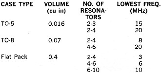
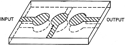
Table 3. Case sizes for monolithic crystal filters. Conventional crystal filters are composed of discrete crystal resonators, inductors, and capacitors with their electrical interconnections. In a monolithic crystal filter, the electrical coupling components and connections are replaced by an elastic coupling medium, namely the quartz plate itself. A monolithic filter consists of a single wafer of crystalline quartz into which are deposited two or more pairs of electrodes, as shown in Fig. 4. Each region between a top and bottom electrode becomes a resonator, with the area of vibrational activity extending outward for a small distance beyond the electrode region. The degree of elastic coupling between adjacent resonators is a function of the distance between electrode pairs. The monolithic filter works this way: A vibration is set up (piezoelectrically) across the crystal's input resonator by the application of a high-frequency electric field. This vibration is coupled elastically to successive resonators until it finally reaches the output resonator. There, the mechanical vibration is transformed by the piezoelectric effect back into electrical energy. The electrical characteristics of monolithic crystal filters are comparable to those of their conventional ancestors. The size and complexity are much reduced, however, resulting in a device that is more reliable and costs less. At 21.4 MHz, for example, a four-resonator monolithic filter housed in a low-profile TO-5 transistor case occupies only 1/60th of a cubic inch and can be bought in large quantities for less than $10 each. By employing these devices with other integrated circuitry, a complete high-gain narrow-band monolithic i.f. amplifier can be packaged in a volume of 1/33 cubic inch. Considerations Affecting Cost The cost of a crystal filter can range from less than ten dollars to several hundred dollars. The major factors determining price are: a. Quantity required - the multiplicity of parameters makes standardization of models impossible, with few exceptions. The engineering cost associated with a new design is normally amortized over the number of units purchased. b. Complexity (number of crystal resonators) - determines assembly and alignment time as well as materials cost. c. Degree of difficulty and special testing requirements - by avoiding the extremes shown on design charts, and by limiting the specification requirements to what is really needed, this cost element can be minimized. Fig. 4. Monolithic filter consists of a single quartz wafer on which two or more pairs of electrodes are deposited. Choosing the Filter
A conventional 4-pole crystal filter used in Talos missile system, with a center frequency of 2.5 MHz, 1.5-kHz bandwidth.
An assortment of monolithic crystal filters covering the frequency range of 3-30 MHz and bandwidths of 500-15,000 Hz. A rather common error in the design of electronic systems that employ sophisticated components is to leap first and look later. If the salient characteristics and limitations of the major components can be borne in mind from the earliest phases of the design, a better and more economical system will result. Therefore, a designer who is planning to employ crystal filters in his system should consider the following areas: a. Fractional Bandwidths: For best performance and lowest cost, choose intermediate frequencies so that the required bandwidths fall between 0.01 percent and 0.5 percent of center frequency. At frequencies from 35 MHz to 70 MHz it is necessary to employ third-overtone resonators, and the bandwidth limits become 0.005 percent and 0.05 percent of center frequency. Overtone crystal filters are more costly than fundamental-mode filters; moreover, it is usually possible to obtain the same bandwidth at a lower center frequency with fundamental crystals. b. Stability with Time and Temperature: Quartz crystals are extremely stable devices. Typical aging rates of high-frequency filter crystals are 5-10 parts per million per year. The variation of frequency with temperature is typically (maximum) ±10 parts per million from 0°C to 50°C, or ±20 parts per million from -40°C to 100°C. For bandwidths greater than 0.1 percent of center frequency, the effects of other discrete components upon the aging and temperature characteristics can be greater than effects of the crystals themselves. The system configuration and filter bandwidths should be chosen to minimize the effects of time and temperature upon system performance. c. Filter Terminations: Conventional (non-monolithic) crystal filters normally contain tuned transformers and inductors, making it a simple matter for the filter designer to shift from the characteristic terminating impedance of the filter to whatever value the user chooses to provide. There are, however, several points worthy of consideration in this regard: 1. If a pure resistive termination is specified, the shunt capacitive reactance should be at least ten times greater than the terminating resistance. 2. A tolerance of ±5 percent on the terminating impedance is normally required in order to obtain best performance. If this is inconvenient for the user to provide, resistive padding can be incorporated into the filter. The result is an increase in insertion loss. 3. A reactive terminating impedance, such as 20 picofarads in parallel with 50 ohms, can usually be accommodated in the design. At 30 MHz, for example, a capacitance in parallel with 50 ohms might be specified as 20 ±10 pF, since 10 pF has a reactance of about 500 ohms. 4. At frequencies above 10 MHz it is generally desirable to specify a low terminating resistance such as 50 ohms. This minimizes the detuning effects of parasitic capacitance. 5. Monolithic crystal filters usually do not contain tuned inductors or transformers. In order for the user to exploit fully the size and cost advantages of the monolithic filter, he must design external circuitry to present the terminating impedance required by the filter. Typical values of terminating resistance for monolithic filters are given in Table 2. The impedances shown are for filters operating in the h.f. band.
Fig. 3 - A single hybrid transformer can be used to serve two filter sections in this circuit. d. Other Specifications: 1. Shape factor, more than any other characteristic, determines the number of resonators required. A Butterworth (maximally flat) design provides 6 dB attenuation at twice the 3-dB bandwidth for each independent resonator, or pole. A six-pole Butterworth filter, for example, would yield a shape factor from 36 to 3 dB of 2:1. A Chebyshev (equi-ripple passband) design will be steeper in cut-off, while a Bessel (maximally flat time delay) design will provide a considerably more gradual attenuation characteristic. 2. Rejection of spurious responses. Inharmonic overtone responses of filter crystals can produce undesired" spurs" at frequencies removed from the passband. Spurious responses generally appear in wider bandwidth filters, especially those comprising only one or two cascaded sections. Inharmonic overtones of high-frequency crystals typically occur at frequencies 1-3 percent above the fundamental resonance. This fact can sometimes be advantageous in the selection of a local oscillator frequency. 3. Ultimate attenuation (approximate rule of thumb): narrow crystal filters - 30 dB per section; wider crystal filters - 20 dB per section; monolithic filters - 20 dB per resonator below 10 MHz, 15 dB per resonator above 10 MHz. 4. Insertion loss: 1 dB to 6 dB, increasing as either the upper or the lower bandwidth limit is approached. 5. Ripple in passband: typically ±0.5 dB over wide temperature ranges; 0 dB for rounded-nose (Gaussian or Bessel) types. 6. Volume: conventional crystal filters - 1-24 cubic inches. Size increases with number of resonators and with decreasing frequency. Monolithic filters - see Table 3.
Fig. 4 - Monolithic filter consists of a single quartz wafer on which two or more pairs of electrodes are deposited. Looking Ahead Within the next five years, manufacturing techniques will be developed for large-scale production of sophisticated monolithic quartz filters. Commercial usage of monolithic filters in home entertainment and ham radio will become economically feasible, resulting in a large market for the devices. Because of its small size, the monolithic filter will be treated more like a miniature integrated-circuit module than a complex subassembly. Unit prices as low as $3-$4 are not inconceivable. Another area of increasing interest is the use of new piezoelectric synthetic crystal materials in filters. Zinc-oxide and other metals are currently being explored as possible resonator materials. The attraction of these materials stems from the fact that greater piezoelectric coupling coefficients exist than with quartz. Sophisticated filters with fractional bandwidths of 1-10 percent could then be achieved in the high-frequency range, closing the gap that currently exists between quartz crystal devices and LC filters.
Posted January 18, 2018 |
|