Connectors for PC Boards
|
|
Here is another in a collection of articles on printed circuit board technology that appeared in the October 1969 edition of Electronics World. Amphenol has been making and driving the evolution of electrical cable, sockets, and connectors since 1932. I have seen their advertisements in many of my vintage electronics magazines, including this one that appeared in these Radio News issues from January and October 1945. A lot of the innovation was driven by military and aerospace quality, reliability, pin density, and weight requirements, and as is always the case, a lot of the benefit redounded to the commercial realm as well. Many of the connector types appearing in this article were still being used during the years I worked in the defense electronics business. During my time as a technician at Westinghouse Electric and Simmonds Precision Instruments, I soldered thousands of wires to those things. Connectors for PC Boards
Mr. Hecker is responsible for the marketing of all standard Amphenol Industrial Div. PC connectors as well as development of new products. He has had twenty years of marketing experience combined with a close association with engineering and production. Previously associated with Cessna Aircraft and E.C.I., he joined Amphenol in 1961. Mr. Novak is responsible for marketing special PC connectors that are developed for specific application programs. With 14 years experience in electronics, he has worked directly with production, industrial, and design engineering departments. He was formerly associated with Hotpoint, joined Amphenol in 1960. By Philip C. Hecker and Charles T. Novak / Product Managers Standard and Special PC Connectors, Amphenol Industrial Div., The Bunker-Ramo Corp. The great variety of connectors makes selection difficult, but it does away with the need for expensive, custom designs. Here is guidance in making the proper connector selection. The constant demand for printed-circuit board connectors to meet specific circuit requirements has resulted in a most awesome collection of configurations, sizes, contact designs, and spacings. Although the variety can make connector selection difficult, it does allow use of existing or "standard" connectors in a large number of applications that might otherwise call for custom designs requiring expensive tooling. Evaluation of several circuit parameters helps to reduce the number of connectors that can be used in a given application. Each connector can offer the right qualities for a wide range of uses. To realize maximum benefit from a given PC connector, however, it must be employed within its best range. One of the most important factors to consider - and one that is often overlooked-is the probable number of insertion and withdrawal cycles.
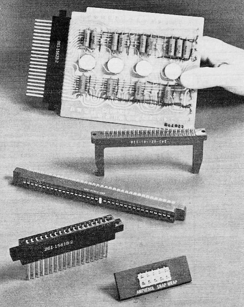
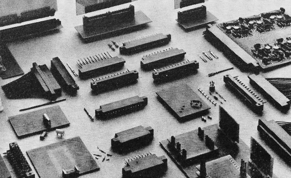
Group of typical Amphenol printed-circuit board connectors. Types of Contacts Contact design and plating determine the number of cycles that a connector can undergo. For applications with 500 cycles or less, several contact designs are used. One type resembles a tuning fork in which the extra-long spring base of the contact and the contact material resilience provide a wide flexing range with elastic reserve. A base plating of copper or nickel is followed by gold plating. These contacts have been tested for 500 cycles of insertion and withdrawal plus a 48-hour salt-spray exposure with only negligible change in contact resistance. Tuning-fork-type contacts can effectively accommodate printed-circuit boards from 0.054- to 0.71-in thickness. Micro-finished contact surfaces afford excellent insertion characteristics and controlled lateral float of the contacts permits accommodation of warped boards with positive continuity of all circuits. For applications requiring more than 500 insertions and withdrawals, bellows-type contacts are recommended. These contacts, formed from phosphor bronze or beryllium copper strip, have a convex contour that concentrates bearing pressure on the mating surface, displaces semiconductive film that may exist, and reduces voltage losses to a minimum. Plating is usually gold over copper or gold over nickel. The bellows action of the contacts absorbs the actual deflection force so that mating surface can withstand in excess of 1000 insertions and withdrawals. Many bellows-type contacts have bifurcated mating surfaces which provide two points of electrical contact per circuit even on irregular surfaces. The bifurcated design also helps to keep the contact on the board during any vibration that might occur. Also, for applications requiring more than 500 insertion and withdrawal cycles, a recently developed connector with precious metal contacts (usually a gold/silver alloy), is applied to a spring member at the point of contact. Thickness and shape of the tip can be varied to suit the application. The entire contact 'itself, except for the tip, can be solder- or tin-plated, eliminating costly over-all gold plate. These contacts have been tested to more than 1000 insertions with no increase in resistivity. The gold is literally where the action is, at the point of contact. Although for most applications the printed-circuit board is inserted directly into the connector receptacle, a plug connector or male contact pins can be fastened, most often by dip soldering, to the board. This is done when the cost of a board with components is particularly expensive or perhaps non-repairable, as in the case of welded or encapsulated components. Connector Materials
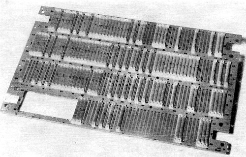
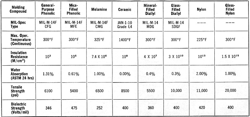
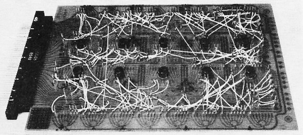
This board with its large number of PC connectors has been designed for Navy's multiple-warhead Poseiden. Specifiers of PC connectors should have a general knowledge of materials available and how they affect not only connector performance but also connector cost. A number of different dielectric materials are used. Phenolic, the most common and least expensive, is intended for applications requiring good electrical qualities with mechanical qualities better than the acceptable minimum. It will withstand a maximum operating temperature of 300° F. See Table 1. Mica-filled phenolic, a low-loss and low-water-absorbing material, is used for applications requiring superior dielectric properties. It has a thousand times the insulation resistance of general-purpose phenolic, but costs only 50 percent more. Cellulose-filled melamine has excellent electrical and mechanical properties and should be considered when resistance to surface creepage is needed. Costs are approximately the same as mica-filled phenolic. Ceramic steatite withstands high temperatures - 1400° F vs 325° F for melamine - is non-hygroscopic and has a low loss factor, but it costs about three times as much as phenolic. Mineral-filled diallyl phthalate is used where dimensional stability of the connector and close tolerances are important. Insulation resistance is excellent - 4 x 10⁷ megohms - and it withstands extremes of humidity and temperature, but it is almost four times more costly than phenolic. Glass-filled diallyl phthalate has generally the same electric properties as its mineral-filled counterpart, but has higher flexural strength. For this reason, it is specified by the military for rugged environments. The cost is approximately six times that of phenolic. The thermoplastic resins, which include polysulfone, nylon, polycarbonate, and ABS, are often used where resiliency is required. Additionally, glass reinforcement can be applied for increased strength and heat resistance. Thermoplastic resins exhibit considerably more flexural strength than the thermosets. From a procurement standpoint, reduced costs can often be realized through shorter cycling times that are inherent in the thermoplastic molding process. Contact Materials & Plating
Table 1. Characteristics of popular dielectrics that are used for printed-circuit connectors. Three basic contact materials are used in PC connectors: brass, phosphor bronze, and beryllium copper. The right choice for a given connector application is a compromise between electrical and mechanical properties. Brass, although it has the best conductivity and is relatively low in cost, will not stand up under excessive insertion and withdrawal cycles. Spring qualities of brass, good at the outset, become less effective as the material age-hardens or crystallizes under stress. Phosphor bronze, twice the cost of brass, has good spring qualities over connector life, but conductivity is relatively low. Heat-treated beryllium copper contacts of the proper design will withstand more insertion and withdrawal cycles than most other non-ferrous spring materials. Conductivity is almost as good as brass but contact cost is about five times that of brass due to both material and tool maintenance. In addition to these three basic materials, a number of other alloys can be used to fit the specific requirements of an application. So many variables, not only the different types of plating materials and combinations, but also plating thickness and contact shape, make meaningful cost comparisons more involved. Gold, probably the most common plating used, is applied in many thicknesses: commercial applications require 20 to 30 millionths of an inch; military specifications call for 50 millionths; and some special applications call for 100 millionths or more. Gold over copper or nickel is generally used in dry-circuit applications requiring low contact resistance and good corrosion resistance. Silver over copper or nickel is used in higher power applications, but corrosion resistance is not as high as gold. Naturally, heavier plating and the number of plating operations increase connector cost. Contact Spacing vs Cost The two main material costs in a PC connector are, of course, contacts and dielectric. Increasing the contact density in a given size and dielectric block results in some saving in dielectric cost but it is relatively minor. The limiting factors in increasing density are dimensional stability of the dielectric material, contact true position requirements, unusual connector shapes, and termination methods used. Cost of a given size connector will rise as contact density increases, but on a per-contact basis cost actually decreases. For example, assume a certain size connector dielectric block costs 25 cents. This block with 15 contacts at 5 cents apiece would cost $1.00; the same block with 30 contacts would cost $1.75. Cost of the connector on a pre-contact basis with 15 contacts is about 6.7 cents, with 30 contacts it is about 5.8 cents. (The saving in dielectric cost in the 30-contact connector is small enough to be considered negligible.) Crosstalk in a PC connector is usually insignificant. Tests have shown that connectors, because of their fixed contact spacing, present fewer crosstalk problems than wiring and cabling. Important MIL-Specs
Popular "card-guide" printed-circuit board connector.
Collection of AMP connectors, showing variety available. A military specification covering many printed-circuit connectors is MIL-C-21097B which outlines electrical and environmental tests as well as connector dimensions to insure interchangeability. For example, PC connectors meeting the spec must withstand thermal shock, vibration, and 50 G's physical shock tests in accordance with MIL-STD-202. An insulation resistance of 5000 megohms at a high-potential test (no breakdown at sea level with 1800 V a. c. and at 70,000-ft altitude with 450 V a. c. applied) are also specified. Although the electrical and environmental requirements of MIL-C-21097B necessarily limit the contact and dielectric materials that can be used, certain materials are specified by type. For example, dielectrics are specified under MIL-M-14F and MIL-M-19833: plating requirements under MIL-C-45204. Contact resistance specified is for a voltage drop of 30 millivolts at a current of 5 amperes. What is most important, however, is that contact resistance, whatever the particular value, remain reasonably constant over the specific connector's rated number of insertion and withdrawal cycles. Some PC connectors are available for commercial applications that meet the performance and environmental requirements of military specifications although they do not necessarily have the exact dielectric or plating thickness specified. These connectors, since they are not restricted to the spec, can provide greater flexibility for design. Choosing the Right Terminating Method Military specifications cover standard solder and crimp pin terminations. Commercial PC connectors can also employ taper-pin type (similar to standard crimp type except that a separate pin is required), percussive welded terminations, and mechanical terminations. The terminating method chosen does not greatly affect the initial cost of the connector, however termination cost variations can be significant. Connectors with solder terminations are designed for direct wiring or for installation on printed-circuit boards, panels, or chassis for dip-solder applications. Taper-pin terminations provide flexibility of assembly procedure and easy modification and repair. Crimp terminations, available with the flexibility of removable contacts, are very economical in applications where programming changes for PC connectors are anticipated. In general, mechanical termination methods - such as solderless wrap and automatic crimp - offer the user significant assembly time savings where large quantities of connectors are involved. For short-run PC board production or applications with a very small number of connectors, soldered terminations are usually the most economical. Individual insert blocks with from one to well over 500 contacts are available with contact centers ranging from 0.025 to 0.250 in. PC connectors are usually referred to as miniature, subminiature, microminiature, and ultraminiature but at present there are few standards that cover these types. In addition to the standard lines of PC connectors on the market, a number of special types have been developed that are available as stock items. For example, card-guide units provide alignment in blind-spot installations and prevent PC board "rocking." Connectors with coaxial contacts, with alternating contact tails that provide more space for terminating, and double-sided connectors are only a few of the special-purpose units available to the designer.
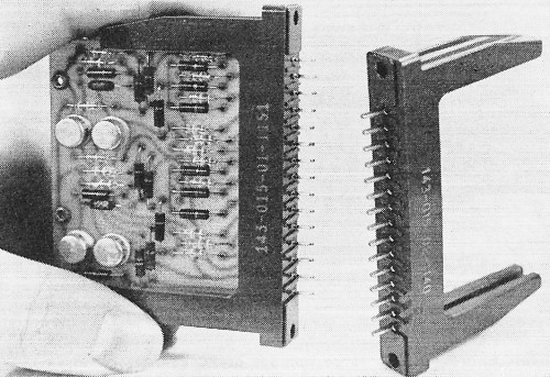
This one-piece, economy-type 40-terminal, card-edge connector is employed in a new automatic writing machine. Two outstanding examples of special-purpose connectors are direct-entry and indirect-entry plate assemblies. Both types utilize an aluminum plate punched to accept thermoplastic modules containing one or more contacts. Direct-entry plate assemblies utilize three- and four-position modules in addition to two-position "L"-shaped card guides; enabling the connector manufacturer to use standard components to produce special configurations. The plate assembly makes framing unnecessary, providing both rigidity and true positioning of contact tails for automatic termination. Indirect-entry plate assemblies are made up of individual single-contact insulators pressed into the plates, creating complete versatility in terms of wrap-tail number, limited only by a designer's imagination. This provides maximum use of contact density, reduction in size of the end product, and economical contact termination. Several manufacturers have been soldering ground and voltage planes on the contact tails and wrapping the balance of the tails. Provisions for grounding contacts are made in both versions. Other special-purpose connectors include PC headers, crimp headers, and male wrap-tail headers allowing for use of any of a wide range of economical termination equipment currently available. Selection of such a special also precludes additional expense of a mold charge. Additionally, these techniques permit repair or replacement of the male and female solderless wrap contact subassembly by simple removal and insertion of an individual contact sub-assembly with hand tools. If a designer keeps the connector in mind at the time he first begins laying out the printed-circuit board, he will most likely to be able to adapt his PC board leads to conform to the contact spacing and over-all width of a standard PC connector. If the connector is not considered until the board is completely designed, there may be no choice but to specify a special connector that not only will require longer delivery time but also involve expensive tooling costs. Designers should provide the PC connector manufacturer with as much information as possible about the unit required: not only the obvious factors of size, number of contacts, current/voltage capacity, but also environmental aspects of the application, contact finishes, dielectric materials, and terminating method preferred. In addition, knowledge of the mounting requirements into the specific end product may enable the connector manufacturer to provide services the user may not have been aware of. Several connector manufacturers are tooled to provide plate assemblies with connectors mounted and to completely wrap, crimp, or solder-terminate the assembly.
Posted September 25, 2017 |
|