Compactrons: Advance in Tube Design
|
|
Refinement of multi-function techniques results in advantages in cost, reliability, and equipment size.
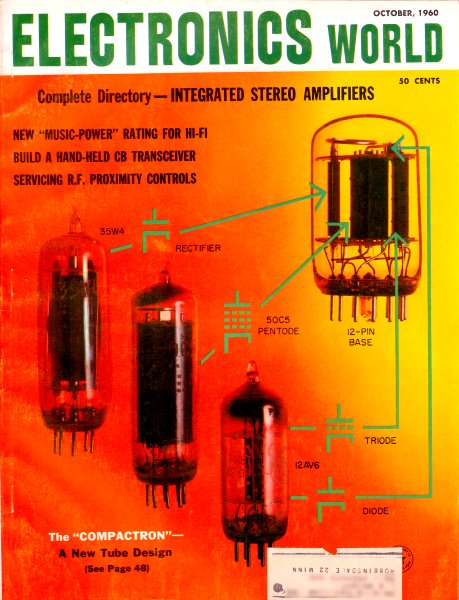
Receiving Tube Dept., General Electric Co., Owensboro, Ky. Promises that semiconductor devices would eventually replace all vacuum tubes have been heard since the demonstration of the first operational transistor. To tube design engineers with the General Electric Co., however, such forecasts have seemed arbitrary. These men saw certain advantages in tubes, actual and potential, that presaged a continuingly important role. Acting on this faith, they embarked on a re-appraisal of the factors involved in tube design to see whether they could not exploit possibilities to a greater extent than had heretofore been realized. Their success has been such that they are reluctant to call the new devices tubes. Thus the vacuum devices now emerging in this separate category are being called "compactrons." What is a compactron? How does it differ from its vacuum-tube predecessors? Part of the answer appears on this month's cover, which features one of the first compactrons to be developed flanked by the three, conventional, miniature tubes (four tube (functions) it replaces. Designed for use in a.c-d.c. table radios, this single envelope houses a power-supply rectifier, an audio-output pentode, a detector diode, and first -audio voltage-amplifying triode (providing the combined functions or the 35W, 50C5, and 12AV6 found in many radios). Combining it with one more compactron that comprises a pentagrid section (converter) and an r.f. pentode (i.f. amplifier), we can put together a tiny, two-compactron radio. In fact, G-E engineers have done just this. The two compactrons shown to the right in Fig. 1, do the work or five conventional miniatures shown to the left in the same photograph. Equivalent diagrams for these units appear just below the tubes and compactrons themselves. A developmental mode of the radio, beside its cabinet, appears in Fig. 3. The manufacturer believes that the advantages which will make compactrons attractive include the following: they will be smaller than tubes, will outperform tubes and transistors, will feature high reliability and life, and will be less expensive than either tubes or transistors. In a stereo hi-fi amplifier, 7 compactrons will do the work of 10 tube or 26 transistors. In the home radio mentioned, 2 compactrons are equivalent to 5 tubes or 7 transistors. In a black-and-white TV receiver, 10 compactrons will match 15 tubes and 3 diodes or 24 transistors and 11 diodes.
Fig. 1 - All functions of the "All-American Five" used in a.c.-d.c. radios (left) included in the envelopes of just two compactrons, at the extreme right.
Fig. 2 - Horizontal mounting of internal structures facilitates low seated height in this multi-function device.
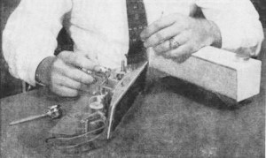
Fig.3 - An engineer experiments with layout of prototype for two-compactron radio. Cabinet is to the right. A working model has since been demonstrated. From the foregoing, a compactron simply would appear to be a single-envelope device in which the technique of housing as many tube functions as possible has been advanced to on exceptional degree. Yet this definition does not take into account all the distinguishing features that make compactron design possible. It also fails to account for the fact that some single-function units are included in the compactron line. To understand this advance in vacuum-tube technology broadly, we must explore specific characteristics one at a time. Beginning at the bottom, we find that the all-glass envelope is designed around a 12-pin circle whose diameter is 3/4 of an inch, larger than that of any conventional tube type. The number of pins, of course, is to take care of multi-function types, but the circle offers advantages even where single-function units are involved. The device will be solidly seated, and it adapts well to printed wiring in that there is adequate space to make connections to all pins. By assigning heater connections to pins 1 and 12, there is space to bring heavier printed wiring to these points if it should be necessary to carry higher current. The wide 12-pin circle also provides a good foundation (or supporting internal structures. For the most part, points of support fall directly under the electrodes to which they are attached. In addition, the extra spacing between pins makes welding of internal connections easier, therefore more reliable. Simplified fabrication will be passed on to compactron users in the form of reduced costs. The development or interelectrode shorting or microphonism during use would appear to be reduced. The compactrons thus far developed use a T-9 bulb with a diameter of 1 1/8 inch, allowing space for multi-function structures. While bulb height will vary, it will be kept down by reason of the fact that the exhaust tip. which usually extends about 5/16 inch above the top of a standard miniature, is placed at the bottom of the compactron between the pins, where it is not wasting space. Thus a receiver designer would have to allow considerably less height, for the most part, than he would for conventional tubes. Compare the height of the compactrons in Fig. 1 with that of the tubes they replace. With a shorter unit, the space occupied will approximate a compact tube. In some cases, like that of a single-function, horizontal-deflection amplifier now being developed, an envelope with a wider diameter (1 1/2 inch, in this case) may be used. However, the pin circle will be unchanged. The wider bulb permits higher power dissipation. Even with the standard diameter, the width permits an interesting possibility. Flexibility in design and other manufacturing advantages may sometimes be obtained by disposing internal structures horizontally, as in Fig. 2, instead of using the vertical mounting common to most tubes. Horizontal mounting also often retains the desirable feature of low tube height. The advantages or the generous pin circle are not exclusively structural. By connecting a plate (or other high-voltage electrode to one pin and leaving two unused pins on either side, a voltage isolation in the order of 10,000 volts can be achieved. This will permit the economy of removing the top cap in many designs (such as a horizontal amplifier, for example), since the relatively simple connection to the base can be made with safety. Thus, even with compactrons limited to a single function because of the high voltages or power dissipation involved, there will be advantages. Improved reliability with reduced cost and size are anticipated. However, most compactrons will be multi-functional devices. Which means lower cost per function will be obtained by the elimination of extra bulbs, extra stems, and extra evacuation procedures. Not the least significant cost-reducing factor is the use of a single heater to activate all of the cathodes (as many as three) in a single envelope. This not only reduces initial cost to the equipment designer but, by keeping heater power requirements and heat dissipation down in use, will further improve reliability. Take the case of the two-compactron radio. The unit shown on this month's cover has a tentative heater rating of 70 volts at 100 milliamperes. Its companion in the a.c.-d.c. radio (the pentode-heptode) is tentatively rated at 40 volts and 100 milliamperes, with the heaters of both compactrons in series across the line. The standard five-tube complement which the pair replaces draws 150 milliamperes - a 50 percent increase in total heater power. In part, this reduction in required heater power is made possible by the use of a copper-base, aluminum-clad, iron plate material in compactron design. The copper layer efficiently reflects heat from the plate back to the cathode, where it is needed. Also, the use of new alloys in making the cathodes increases heat transfer from heater to cathode, improving efficiency further and cutting warm-up time. So much for the features that characterize the compactron type. To what extent have results already been achieved? With many types in various stages of development, G-E has already announced pilot production of six units, available to equipment manufacturers on a sampling basis. In addition to the two for the radio, there is a compactron with two triodes and two diodes. It is intended for TV use as a combined horizontal oscillator, phase detector, and a.f.c. unit. A compact beam-power pentode, for use as a horizontal-deflection amplifier in TV, is one of the few single-function types. Here are some of its characteristics: plate dissipation, 12.5 watts: perveance, 320 ma. at 60 volts; maximum plate voltage, 6500 volts; heater voltage, 6.3 volts; and heater current, 1.2 amperes. A companion "single" type is a damper diode, for use in television, with an average damper current of 165 ma. and a maximum heater-cathode voltage rating of 5000 volts. Last of the six initial units is a combined vertical oscillator and deflection amplifier (two dissimilar triodes) for TV. Now in the works are many other types. These include an alternate unit for use as the TV horizontal oscillator, phase detector, and a.f.c. correction circuit that will consist of two diodes, a triode, and a pentode. Nor are equipments other than TV receivers being neglected. Compactrons especially designed to meet the requirements of auto-radio design are being developed. All of these are expected to be in production within the next year. And this may simply be the beginning. With growing technical expertise, it is hoped that the advantages already established will be enhanced even further as new designs come out. One possibility that design engineers are actively evaluating is that of including within the glass envelopes circuit elements that are usually added (resistors, capacitors) externally in the case of tubes. If this is in fact done, it can further enhance miniaturization and cost savings. Inclusion of such elements inside the vacuum may also pay noteworthy dividends in the form of improved reliability. A possible disadvantage is the replacement cost when a multi-function compactron, Instead of a single tube, becomes defective. However, G-E engineers feel that other savings may at least cancel this out. Lower initial equipment cost, cost per function, and reliability will be factors. Ultimate success or the line is probably in the hands of equipment manufacturers, whose use of compactrons in less expensive, more efficient designs will be a key factor.
Posted August 29, 2019 |
|
 By Philip E. Hatfield, W9GFS