"Chirp" A New Radar Technique
|
|
Pulse compression (aka 'chirp') radar was invented in the 1950s by Sperry and a couple other defense contractors. It was new enough by the time the radar I worked on as a technician in the USAF that it was not incorporated. Our MPN-13 and MPN-14 radar systems used simple single-frequency pulses. Pulse compression employs a swept frequency within a fairly narrow bandwidth to exploit the benefits outlined in this 1965 Electronics World article. If you were to listen to the signal used to sweep the RF pulse in frequency, it would sound a lot like a bird's chirp, hence the name. Treatment by author Donald Lancaster is fairly heavy in that it fearlessly presents the mathematical concepts of sin(x)/x waveforms, Fourier transforms, and weighting. He references Skolnik, Ridenour, et al. Even so, it is a quick read that provides a good introduction to chirp radar. "Chirp" A New Radar Technique
Using a swept-frequency approach, this new radar has greatly improved range and target resolution over conventional pulse methods and is also less susceptible to present-day jamming techniques. The dark veil of military secrecy has been lifted on a most amazing and powerful radar technique called pulse compression - nicknamed "chirp." By applying mathematical techniques to a conventional pulsed radar, range and resolution can simultaneously be increased while at the same time using less peak input power. The radar also becomes significantly harder to jam, and much more immune to certain forms of noise. Further, the requirements for very high power-supply voltages can be reduced. Chirp is perhaps the most significant radar advance of recent years. Its improvement upon radar performance can be as high as several hundred times the capability of conventional techniques. There is no apparent limit to the ultimate attainable improvement.
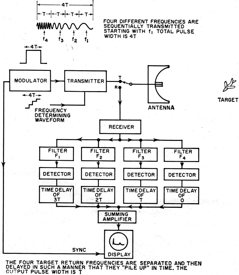
Fig. 1 - A four-frequency radar will have four times the resolution of a conventional radar of equal range if the target returns are processed as shown. This is the basis of "chirp." The majority of presently used radars are of the pulse type, i.e., systems that transmit a very large burst of radio frequency energy for a very brief interval and then wait for echo returns from any targets within range. From these echoes, the position, size, type, and movement of a target may be determined. Pulse radar uses extend from weather observation, airport flight control, travel aids for the blind, and vehicle collision devices, to the military long-range mapping radars, battlefield radars, and other detection systems. In a conventional pulsed radar, a narrow, high-voltage pulse is applied to an r.f. tube such as a magnetron which briefly oscillates at a fixed microwave frequency. (Microwaves are used for radar because physically small antennas with good directional properties can be obtained only at very high frequencies.) This microwave pulse is first transmitted. A receiving antenna and detector then monitor for target echoes, and these returns are displayed on a cathode-ray tube whose sweep is synchronized with the transmitted pulse. The time it takes an echo to get back to the receiver is directly related to the distance between radar and target. The radar burst travels at the speed of light, or roughly 1000 feet in a microsecond. Since the transmitted signal has to make a round trip, each microsecond of delay accounts for a target-to-radar distance of 500 feet. Another pulse is transmitted after all the initial echoes have had a chance to return. This process is repeated again and again, thus producing a continuous plot of targets. The bigger a target is, the more energy it will return and the brighter it will appear on the display. Further signal processing, based upon the Doppler effect, can determine whether the target is moving or stationary, and if moving, in what direction and how fast. Chirp becomes valuable only when the ultimate limits of the conventional pulse radar fall short of the required performance in range and resolution. Range of a radar is the maximum target distance at which reliable echo returns can be expected, while resolution is its ultimate ability to discriminate between two closely spaced targets while still giving two distinct return echoes. Range is determined by the amount of r.f. energy being transmitted. This is equal to the pulse height (power) multiplied by the pulse width (time). (Power X time = energy.) This is equal to the area of the transmitted pulse. The range of a radar is proportional to the fourth root of the transmitted energy because both radar and target transmit energy in a square-law manner. To double the range of a radar, the transmitted energy must be increased by a factor of 24 or 16 times. Resolution of a radar is determined solely by transmitter pulse width. Two targets separated by less than the pulse width will give a single echo return because the end of the transmitted pulse will be reflected by the near target at the same time the beginning of the transmitted pulse is being reflected from the far target. Range and resolution, therefore, are two radar system requirements in opposition to each other. To obtain resolution, the transmitted pulse must be as narrow as possible to obtain range, the area of the transmitted pulse must be a large as possible. These two taken together result in a very narrow, extremely high-power r.f. pulse. System and component capabilities then enter the picture. The transmitter tubes are asked to provide very brief pulses of extreme power, sometimes as high as several megawatts. The narrow duty cycles used in very brief pulses are inefficient. There is also an upper limit to the maximum voltage power supply that is practical in an airborne application, due to arcing problems. Voltages in excess of 40 kV. become quite troublesome. Higher-current transmitting tubes can be used, but there is a limitation here also. The resonant cavities of the tubes must be of a small size if they are to produce microwaves; there is also a limit to the maximum current-produced heat that will not melt the tube structure. This was the problem before chirp. What was needed was a method of increasing the transmitted pulse length, thus increasing power, yet not degrading the resolution. How Chirp Works
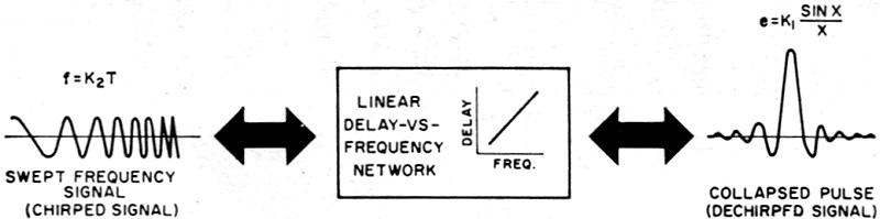
Fig. 2 - If a linearly swept frequency is fed to a linear display vs frequency network, the different portions of the signal will be delayed long enough so that all frequencies will pile up into a narrow output pulse. This network can also be used in reverse. To explain chirp, consider the imaginary system of Fig. 1. Instead of transmitting a single frequency pulse, the radar now transmits, in turn, four discrete frequencies forming the over-all transmitted pulse. The first frequency (f1) is transmitted for a time T, then frequency f2 for a time T, then f3 for time T, and finally f4 for time T. The time length T (in microseconds) of each frequency of transmission is identical. The receiver uses four separate filters and detectors for the target-returned frequencies f1, f2, f3, and f4. The outputs of the four detectors are then time-delayed in such a manner that the outputs all "pile up" or coincide in time. Thus, f1 is delayed for 3T seconds, f2 for 2T seconds, f3 for T seconds, and f4 is not delayed. The summed output pulse width is T seconds. However, the original transmitted pulse was 4T seconds long; therefore, the resolution has been increased by a factor of four with no decrease in transmitted energy. Resolution is determined by what each individual detector receives, which is a pulse only T microseconds wide. With a conventional radar, the return pulse would have to be 4T microseconds wide. This 4:1 improvement does not have to mean heightened resolution. It can just as well be a 4:1 increase in transmitted energy resulting in increased range with no change in resolution. By the fourth-root law, this would extend radar range by a factor of 1.20. Or, if both the conventional range and resolution were satisfactory, the four-frequency modulation technique reduces the peak power required by a factor of four, thus greatly simplifying system power supplies. The more frequencies that are used and the less time spent at each frequency, the better will be the result. The limit of more and more frequencies is a linearly swept signal. The delay required at the receiver would then be a linearly increasing delay vs frequency device. This is the foundation of chirp. A chirp radar is one that transmits a swept-frequency signal, receives it from a target, and then delays the signal in such a manner that the return signal is compressed in time to give a short, intense return signal. The swept signal is called the chirp signal. The final narrow pulse is called the dechirped, collapsed, or compressed signal. When a linearly swept or chirp signal is run through a linear delay vs frequency network, as in Fig. 2, the various frequencies are delayed so that they pile up in time at the output. This piling up does not result in a perfectly rectangular pulse, but instead the signal assumes the shape of the pulse shown in Fig. 2. This pulse is called a (sin x/x) pulse because this is its mathematical shape. (A mathematician at this point might correctly point out that chirp radar signal processing is nothing but a means of taking the Fourier transform of the rectangular energy spectrum of the transmitted signal. This is where the (sin x/x) pulse comes from.) If the sidelobes of this waveform are eliminated, a very good approximation to a conventional rectangular pulse results.
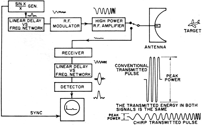
Fig. 3 - A "chirp" radar system requires much less power than a pulsed radar to produce equal range and target resolution.
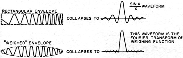
Fig. 4 - The sidelobes of the collapsed chirp pulse can be significantly reduced by the "weighting" technique. A linear delay vs frequency network is a reciprocal device. This means that a (sin x/x) pulse can be fed through the network to produce a swept-frequency signal or a linearly swept signal can produce a (sin x/x) pulse. In a chirp radar, a (sin x/x) pulse of the desired resolution is generated and passed through the network to produce a swept-frequency signal. This signal is then transmitted at microwave frequency at the required high-power level. The echo returns are then received and passed through a second delay network to obtain return echoes the same shape and resolution as the initial (sin x/x) pulse. In the process, a significant improvement in range, resolution, and peak-power requirement is obtained. The ratio of lengths between the swept signal and the (sin x/x) pulse is called the chirp ratio and is a figure of merit of the expected improvement of a chirp system over a conventional system. The chirp ratio can be as high as several hundred although the minimum chirp ratio meeting system requirements is always chosen, since the wide receiver bandwidths needed add greatly to system cost and complexity. A chirped radar is compared to a conventional radar in Fig. 3. Here the chirp ratio is about five. Although both radars have equal range and resolution, only 1/5 the peak power is required using the chirp system. There are a number of ways of generating the swept signal. There is a distinct advantage to the method of starting with a (sin x/x) pulse and passing it through a delay network. If the same network is used for both chirping and dechirping, any system non-linearities or distortions cancel, giving a cleaner signal than would otherwise be possible. This is called a matched-filter technique, a tremendously significant radar tool. It is possible also to actively generate a linearly swept frequency without using a delay network. This method is simpler but requires very careful control of system linearity and sweep rate. There are likewise a number of dechirp, or pulse compression, methods. Certain ultrasonic aluminum delay lines, as well as special quartz delay lines, can directly produce the required delay vs frequency characteristic. A delay line that delays various frequencies different lengths of time is called a dispersive line. A second method uses a bridged-T network. By carefully "stacking" the right number of bridged-T's, with properly chosen delay widths and center frequencies, a linear delay vs frequency can be very closely approximated. The complexity of this method is offset by the wide bandwidth and adjustability attainable. There are some more subtle but equally significant advantages of chirp. Note that a chirp system has to have a much wider receiver bandwidth than a conventional pulsed radar of equal peak power. Also note that the energy transmitted is distributed over a much wider range of frequencies. This makes the radar relatively immune to jamming. There is another significant advantage of chirp. The delay network will only pile up, or compress, one particular swept frequency whose slope and bandwidth exactly match the network. Random signals fed into the delay network will not pile up and will come out of the network with the same amplitude they had when they went in (assuming a lossless network). However, the real signal will pile up by the chirp ratio and increase in amplitude by the same factor. This means that the signal-to-noise ratio of the radar echo returns is considerably improved going through the delay network. One thing remains - the side lobes on the (sin x/x) pulse. By controlling, or shaping the amplitude of the swept-frequency signal before or after it is transmitted, the side lobes can be very greatly reduced in magnitude (Fig. 4). This increases the radar dynamic range. For further reading in chirp and chirped radars, the references listed below might be of interest. Most of the references assume an extensive knowledge of advanced mathematics and, with the exception of reference 1, might make fairly difficult reading. Sources 1 and 2 are excellent general radar texts, while the others deal specifically with chirp and pulse compression. References 1. Ridenour, L. N.: "Radar System Engineering," McGraw-Hill Book Co.,New York, 1945, or Boston Technical Lithographers, Lexington, Mass., 1963. 2. Skolnik, M. I.: "Introduction to Radar Systems," McGraw-Hill Book Co., New York,1962. 3. Klauder, J. R. et al.: "The Theory and Design of Chirp Radars," Bell System Technical Journal, July 1960. 4. "IRE Transactions on Military Electronics," Vol MIL-6, April 1962. Special issue on signal processing radar. 5. Omeara, T. R.: "The Synthesis of Band-Pass All-Pass Time-Delay Networks Using Graphical Approximation Techniques," Hughes Research Report No. 114, Hughes Research Labs., Malibu, California.
Posted March 31, 2020 |
|