Bandwidth Compression for Efficient Digital Communications
|
|
Bandwidth compression is a major strategy in today's seriously overcrowded communications spectrum. Compression has occurred both through m−ary digital modulation and through downsampling of voice - the latter of which is partially responsible for the crappy quality of cellphones versus old fashioned copper landline telephones. The mathematics of sampling theory are complex to say the least, and its ability to accommodate reliable communications in the midst of incredibly dense interference is amazing. This article was written in 1969 near the beginning of digital communications. Probably the earliest form of bandwidth compression was adoption in the 1920s of single sideband AM, where the required bandwidth was instantly reduced to half. Some applications that still need - or work more reliably with - a sampling of the carrier frequency for demodulation use vestigial sideband modulation, which adds a bit to the occupied bandwidth of each channel. Bandwidth Compression for Efficient Digital Communications By John W. Stumpe / Associate Principal Engineer, Radiation Inc.
In the past five years, digital communications techniques and facilities have doubled and tripled, and current indications are that this growth will continue at the same rapid rate for years to come. This article discusses some of the reasons for this maturation, investigates some of the advantages and disadvantages of digital transmission, and discusses various bandwidth compression techniques that can be used to overcome a great number of the problems.
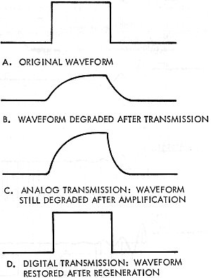
Fig. 1 - During transmission, waveforms are degraded due to characteristics of the transmission media, but in a digital system, it's relatively easy to restore the original waveshape. Solid-state circuitry and digital computer development have contributed greatly to the current boom in digital communications. Now it's possible to build complex high-speed communications systems that operate automatically or under program control to speed the flow of message traffic from user to user. Actually, digital communications techniques have been in use for hundreds of years. The drums of the African natives and smoke signals used by the Indians can be classified as crude forms of digital communications. And of course, pioneers in the West depended upon the telegraph to provide a rapid means of message transmission. With the advent of radio transmission, however, Morse code became the standard means of long-distance communication, until the teletypewriter replaced the telegrapher, and now it's being used in almost every country of the world. Today, vast networks such as Western Union use digital techniques to move huge volumes of messages. The techniques described in the preceding paragraph are all characterized by the fact that the transmission is in message form. For voice transmission as well as facsimile and similar types of continuous data, analog techniques have been used. The analog processes generally are simpler, require less complicated hardware, and use less bandwidth for transmission. In fact, the digital transmission process is relatively inefficient. For example, consider a single telephone channel using a nominal bandwidth of 4 kHz which we want to convert to digital format. An analog-to-digital converter will be required to represent the voice signal as a synchronous pulse-code-modulated (PCM) bit stream. Six-bit quantizing at an 8-kHz rate, which is typically used to provide reasonable quality, results in a 48 kilobit/second bit steam. At the receiver, synchronization circuitry and a digital-to-analog converter with appropriate filtering are required to reproduce the voice waveform. Why, then, use digital transmission if it requires more complex equipment and more bandwidth? There are two reasons. The first and most important to the commercial user is graphically illustrated in Fig. 1. The original waveform to be transmitted is shown in A. The waveform will suffer some degradation during transmission due to the characteristics of the transmission medium, as shown in B. If transmission must be accomplished over significant distances, the waveform must normally be amplified at periodic intervals. When using analog transmission, linear amplification is required in order to preserve the wave-shape. Therefore, any noise or distortion that falls within the passband of the signal is amplified right along with it, as shown in C. The end result is a noisy signal that may vary considerably in amplitude if fading is present in the transmission channel. When using digital transmission, however, the waveform can be regenerated and retimed by simple repeater amplifiers as shown in D. As long as amplitude variations and noise are not sufficient to cause erroneous receiver bit decisions, the digital signals will provide noise-free communications of proper amplitude. The major trade-off here is transmitted signal quality vs bandwidth and equipment cost. The second important reason for employing digital transmission is to allow the use of digital devices for secure transmission. This condition is, of course, a military requirement where the need for security is paramount.
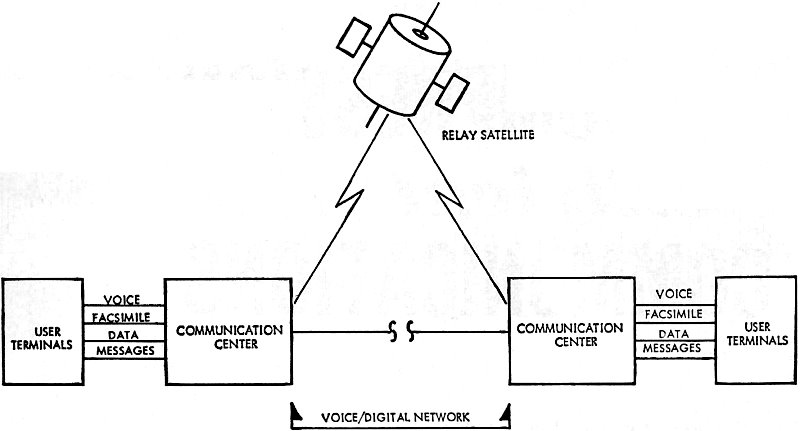
Fig. 2 - Advanced communications system may use satellites as well as land lines and microwave to transmit digital data. Fig. 2 shows an advanced communications system. This system is representative of digital systems processing voice, facsimile, data, and message information through communications centers and digital transmission links or satellite relays to other communications centers. Common factors that must be considered in the design and operation of these systems are as follows: • Bandwidth Utilization. This is of primary importance. Because of the crowded spectrum and limited facilities, it is necessary that we make maximum use of all available bandwidths. • Transmission Security. Security is to the military. To meet security transmission is a must. • Information Integrity. Unless data is transmitted properly, it is going to be of no value to the user. We must insure that the information gets to the user on time and in the proper form. If there are errors in the transmission, the data becomes meaningless. Delays are caused because the information must be retransmitted or some alternate means found for passing the data along. • Vulnerability. This is also important, not only to the military from the standpoint of anti-jam capabilities, but to the commercial user as well, when one considers the problem of insensitivity to noise, interference on telephone channels, and other similar effects. Adaptive Systems
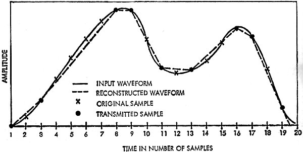
Fig. 3 - Evolution of digital data transmission systems. Adaptive data systems have characteristics which lend themselves to solving the previously mentioned problems. An adaptive data system is basically classified as a data transmission system which selects and transmits only those points in a data waveform which cannot be predicted (within a given accuracy) at the receiver. This is the basis for redundancy reduction techniques for bandwidth compression which this article discusses. Data which does not add significant value to the received information is considered to be redundant. Therefore, it is not necessary to transmit this data if the values can be predicted at the receiver. Consequently, redundancy reduction techniques involve looking at the information as it is being processed to determine which data points must be transmitted; then only significant data points are put into the transmission link. This is the means by which the bandwidth compression is accomplished. Fig. 3 illustrates the application of these techniques. The top figure shows an analog waveform which would normally be transmitted (if it were voice) on a standard telephone channel. If PCM techniques are to be used for digital transmission, this waveform would be sampled at a synchronous rate high enough to reproduce the frequencies present in the waveform, converted to digital format. If typical voice PCM requirements are met, the sampling rate of a 3-kHz voice signal would be fixed at approximately 8 kHz. To maintain adequate quality, each of these samples would be converted to a minimum of 6 bits of digital information. With 6-bit sampling at the 8-kHz rate, a 48 kilobit/second stream must be transmitted. This system now requires the equivalent bandwidth of 12 telephone channels in order to transmit the information. But, through the application of reduction techniques, only significant samples that provide specific information are selected for transmission, thereby accomplishing the required compression. Fig. 4 illustrates actual compression operations. The signal is effectively represented at the receiver as a straight-line approximation of the input waveform (shown by the solid line). The dotted lines show the interconnected straight-line segments that are generated at the receiver to represent the original input waveform. The points which cannot be predicted at the receiver are represented by the solid dots at the segment intersections. Note that the 20 original samples required for PCM transmission have now been reduced to only nine samples, thereby providing significant savings in the over-all operation.
Fig. 4 - In the first-order redundancy reduction method, waveform is reproduced by using straight-line approximations.
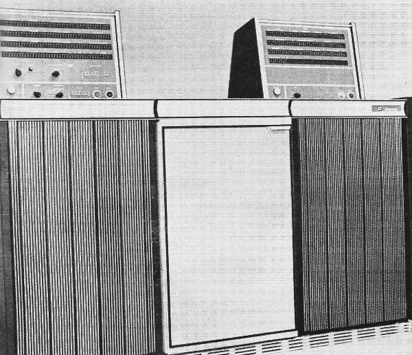
Fig. 5 - A data analyzer used to evaluate reduction techniques. To enable the receiver to reconstruct the transmitted waveform, some additional data is sent with each non-redundant sample value. This data consists of the number of sample intervals which have occurred between the present sample and the last transmitted sample, and is called the "time tag." In Fig. 4, the value transmitted at sample time 8 would carry a time tag of 5. With the amplitude values occurring at sample times 3 and 8 and the proper number of sample intervals between the two values, the receiver circuitry can now compute values for the intermediate samples that were not transmitted, thus reconstructing an approximation of the input waveform. To use the results of the redundancy reduction for bandwidth compression, it is necessary to place the non-redundant samples that are occurring at non-synchronous intervals into a storage buffer. Then the data points can be clocked at the lower synchronous rate which is equal to the average rate-of-occurrence of the non-redundant samples. The system shown in Fig. 5 is called a Data Management Analyzer. This is a laboratory tool which was designed specifically for the purpose of evaluating effects of various redundancy reduction techniques on actual data. General-purpose computers could have been used for evaluation purposes; however, two high-speed units would have been needed to accomplish the operations performed by this equipment. In addition, the computers would require extensive programming support for the various processing operations. The DMA processes volumes of data in a very short period of time, at low cost, and provides the flexibility which the operator needs to change parameters and quickly evaluate different processing techniques. This system has been used to evaluate telemetry data, biomedical data, and facsimile data, and was the system used to perform the feasibility studies for the digital voice compression program described here. Fig. 6. Block diagram of RACE adaptive compression system. Some of the studies of data compression techniques involved various classes of pulse-code-modulated (PCM) telemetry data. For example, three channels of rocket booster data were studied to determine how much bandwidth reduction was possible using adaptive techniques. The three channels included a flow measurement, a temperature measurement, and an ignition pressure measurement. The measurement period studied was 220 seconds and included first-stage cut-off. Using the Fan method (this will be explained in greater detail later), a reduction of 161 to 1 is possible without any loss of data. Originally, the total PCM system was made up of 216 ten-bit channels, each sampled 12 times per second. This required a transmission bandwidth of approximately 13 kHz. If all the channels could be reduced like the three studied, the total bandwidth could be reduced to approximately 80 Hz. Weather pictures (facsimile) like those taken by a camera in the Nimbus satellite are usually reproduced on the ground by analog techniques. But if the picture is reproduced by converting the analog signal to synchronous PCM at a high enough sample rate, a good quality picture is obtained. Through adaptive techniques, bandwidth compression of more than 9 to 1 over synchronous PCM is possible and essential details in the picture are still apparent and usable. Now here is the important result of all this. If a system such as this is applied to a spacecraft requirement, thousands of dollars can be saved, because by reducing the bandwidth, the power required for transmission in the vehicle is reduced and a reduction in vehicle power means a reduction in weight. A reduction of the payload's weight is multiplied many fold in the total booster weight and the power requirements for the booster. The net effect is a significant cost saving in the total vehicle system. NASA's Marshall Space Flight Center, Huntsville, Alabama used a system called the Telemetry Redundancy Analyzer System to study telemetry data. This particular system was capable of handling up to 32 channels of input Information and implemented five different compression algorithms.
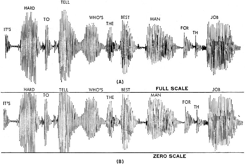
Fig. 7 - (A) Typical voice pattern. (B) An a.g.c. circuit limits the input signal swing and assures maximum signal level. Document Transmission Bandwidth Compression studies have also been made. These programs were aimed at reducing bandwidth requirements for high-speed document transmission systems. Today, typical systems require transmission bandwidths of about 240 kHz for a document transmission rate of six pages per minute. These circuits are of limited availability and very expensive. If a compression ratio of 5 to 1 can be obtained, the documents can be transmitted at the same page rate, with no degradation in quality, over a 48-kHz channel. The cost saving in transmission lines alone is 7 to 1. When line lengths are long, this saving can amount to millions of dollars within a year's time. The study proved conclusively that an average compression ratio of 5.8 to 1 can be obtained on the type of documents which were processed. These programs are now continuing with the evaluation of other compression techniques to determine whether it's possible to attain higher compression ratios with additional cost savings. More recently, studies have been conducted in digital voice-compression techniques. The Vocoder is probably the most widely known device for reducing voice bandwidth requirements. Vocoder systems provide significant improvements in transmission efficiency with typical transmission rates of 2400 to 9600 bits/second. However, they produce a voice commensurate with their bit rates, i.e., the lower the rate, the lower the quality. Even at 9600 bits per second, the quality is still not as good as a 48-kilobit PCM signal because the voice is produced by a frequency synthesis process rather than by waveform reproduction. While intelligibility may be excellent when using such devices, the "natural" quality of the voice is destroyed.
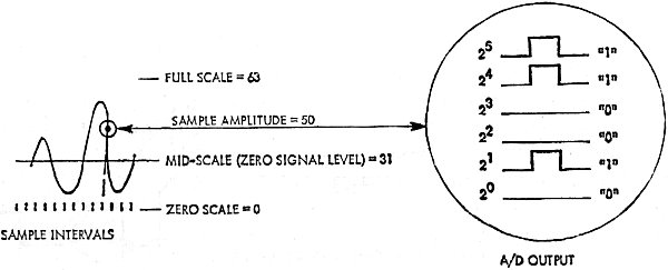
Fig. 8 - This is an example of the digitizing process. Here a specific signal amplitude is converted to a six-bit word. In an effort to improve digital voice transmission, the Defense Communications Agency (DCA) has sponsored several research and development study programs in digital voice transmission. The goal of one of the study programs was to determine the feasibility of providing high-quality digital voice communications at bit rates of 9600 bits per second or less through the use of selected redundancy reduction techniques. Again, the DMA was used to process the input voice after digitizing, to simulate the transmission of the compressed digital data, and to reconstruct the original waveform at the receiving end. To provide data for quality evaluation, tape recordings of both the input and the reconstructed output waveforms were made simultaneously on a dual-track recorder. Although quality evaluations were made by listening to the test tapes, numerical data was also recorded to indicate the compression ratio attainable on each test sample. These tests were performed using two redundancy reduction algorithms known as the Extended Step Method and the Fan Method. The Extended Step Method is a zero-order process whose usefulness lies chiefly in the simplicity of the hardware required for implementation. The Fan Method, which is a first-order process, requires additional hardware, but provides better over-all quality and compression performance. Listening comparison tests indicated that quality equivalent to that produced by a 48-kilobit PCM system was feasible using the redundancy reduction techniques described in the previous paragraphs. Based on these test results, a prototype system was built. The prototype system is called Radiation Adaptive Compression Equipment (RACE). A detailed block diagram of a single full-duplex RACE terminal is shown in Fig. 6. Input signals from a standard desk telephone are applied to an a.g.c. amplifier to provide gain adjustment for various speaker levels. After filtering to eliminate extraneous noise, the signals are converted to a digital format and fed into the bandwidth compression circuitry and the storage buffer. From the buffer, parallel words are converted to a serial bit stream and fed to a data modem for transmission. On the receive side, the serial bit stream is converted back to parallel format and placed in the buffer. Data flows from the buffer into a reconstructor where the original waveform is regenerated in digital form. The signal then passes through a digital-to-analog converter and output filter to smooth the waveform, and through the amplifier to the receiver. Fig. 7 A shows what a typical input voice signal looks like. This is one of the test sentences from a test tape used in the feasibility study. Notice that there are very large variations from word to word. This is typical of individual speakers. In addition, there are significant differences in the dynamic range of various speakers. Thus, to attain the most efficient performance with the compression processes, the input must be normalized. This is accomplished by the a.g.c. circuit which limits the swing of the input signal, as shown in Fig. 7B. Note that in some instances small portions of the waveform peaks have been clipped. This can be done without significantly affecting the quality of the voice signal and insures that the system will operate at a reasonably constant amplitude level, no matter who is using it. The input information is sampled in the analog-to-digital converter. At each of the sample points, the actual amplitude value (in this example, the value is 50) is converted to a six-bit digital word as shown in Fig. 8.
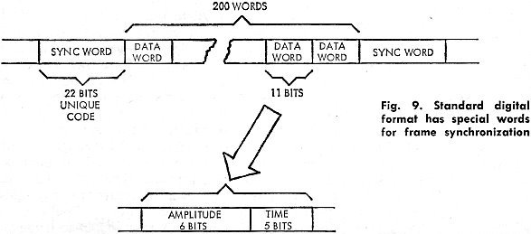
Fig. 10 - Standard digital format has special words for frame synchronization.
Fig. 10 - At the receiver, information is converted 10 a straight-line approximation through Fan reconstruction. After the compression process is complete, the information will have a standard digital format that looks just like typical computer data as far as the transmission facilities are concerned. The standard data format shown in Fig. 9 has sync words to establish frame synchronization and data words containing specific information on each data point transmitted. Therefore, the system can interface with a common digital data net for transmission. As far as the transmission facilities are concerned, they couldn't care less whether the information is voice, data, or teletypewriter traffic. They all share a common format which permits the use of a single common, inexpensive system operating in a narrow-band mode. At the receiver, information is converted back to the straight-line approximation through the process shown in Fig. 10. Two transmitted points are shown. In order to reconstruct this straight-line segment, it is only necessary to know the respective amplitudes of the two end points and the time duration between the two points. By calculating the slope of this line, the value of each of the intermediate points can be computed by the reconstructor. Note that this computational process is accomplished at a rate which is twice the original sample rate. This provides additional gains in quality by making the output filters much more effective during the smoothing process and giving a pleasing output waveform.
Posted November 29, 2017 |
|
 Voice communication is not as reliable as digital
and also lacks security. Digital transmissions, however, require wider bandwidth but
new compression techniques make such systems more efficient, thus cutting the cost of
transmission lines.
Voice communication is not as reliable as digital
and also lacks security. Digital transmissions, however, require wider bandwidth but
new compression techniques make such systems more efficient, thus cutting the cost of
transmission lines.