|
February 1966 Electronics World
 Table of Contents Table of Contents
Wax nostalgic about and learn from the history of early electronics. See articles
from
Electronics World, published May 1959
- December 1971. All copyrights hereby acknowledged.
|
Yes, the old days of over-the-air
broadcasts and analog television could be a pain. Perfect adjustment of the antenna
and TV controls one day could be totally useless the next day or even later the
same day. Atmospheric and physical variations can change suddenly and significantly,
affecting both radio and television. Proper separation and processing of horizontal
and vertical synchronization of the video, color and intensity, and audio by the
TV's electronic circuits depended on the right combination of antenna, and lead-in
cable. The advent of semiconductors in place of vacuum tubes helped stabilize the
television's role in viewing quality and lessened the overall irritation level,
and the introduction of cable-based and then satellite-based programming distribution
to reduce irritations to the point where most people never had a problem. That
said, I would happily return to the days of yore and suffer the aforementioned inconveniences,
to enjoy a time when the content was significantly less rude and crude, and patriotic
and traditional family-based shows were by far the rule rather than the exception.
More than two decades have passed since Melanie and I watched broadcast TV of any
sort with the exception of a couple programs - "24," "Chuck," and "NUMB3RS." These
days we only watch shows from the 1950's through 1980's on DVD sets. Our sole TV
is a 26", circa 2007 model with a built-in DVD player. It's not the technology we
reject, it's the content.
Designing an All-Channel TV Antenna
 One of a line of antennas employing the
design principles described. One of a line of antennas employing the
design principles described.
By Paul E. Mayes
Technical Consultant
JFD Research & Development Laboratories
Evolution of the design of an antenna that will cover both v.h.f. and u.h.f.
TV channels and that employs but a single downlead.
The emergence of u.h.f. television broadcasting brought about by Federal legislation
has presented antenna designers with a new challenge. The advantages of an all-channel
(v.h.f. plus u.h.f.) antenna in areas with intermixed telecasting are apparent.
Only one lead-in need be run from antenna to set. Installation time is reduced since
it is not necessary to mount separate v.h.f. and u.h.f. antennas. The possibility
of scattering from one antenna affecting the performance of the other is eliminated.
Although separate v.h.f. and u.h.f. input terminals are still present on most sets
now available, single-input sets will be the inevitable result of improved tuner
design. For multiple-input sets, efficient signal splitters can be used at the receiver
to provide separate v.h.f. and u.h.f. signals (also to drive an FM tuner).
Broadband Antenna Arrays
One of the first problems encountered in attempting to design an all-channel
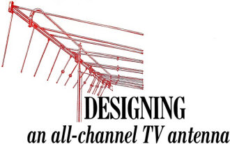
Fig. 1 - (A) Resistive and (B) reactive components of the input
impedance of a center-fed linear dipole antenna element.
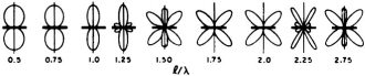
Fig. 2 - Radiation patterns of linear dipoles (center-driven
to produce in-phase currents in both halves of the element) having various lengths
and with l/d ratio greater than 100. Antennas are indicated by the dark horizontal
lines shown.
(2-83) antenna is that of frequency response. Although variable frequency testing
and the resulting ratings of audio components are familiar to most, similar data
showing antenna performance may be new to many. The problem can be illustrated by
considering the input impedance versus wavelength characteristics of a simple linear
dipole as shown in Fig. 1.
The horizontal scale shows the ratio of dipole length (l) to wavelength
(λ). The vertical scale on the upper graph is the resistive part of the impedance;
on the lower graph, the reactive part. Note that only near the resonances of the
dipoles which occur approximately at l/λ = (2n+1)/2(n = 0,1,2, etc.)
is the impedance almost totally resistive and at the same time small enough to be
easily matched to the resistive characteristic impedance of a common low-loss transmission
line. The frequency band over which the reactance can be maintained at low values
is dependent upon the cross-section of the dipole. However, even for very "fat"
dipoles as indicated by small values of the length-to-diameter ratio, l/d,
the variation in input impedance may not be tolerable. The relative bandwidth is
often defined as the difference between the frequencies at which the reactance is
equal to the resistance at resonance divided by the geometric mean of these frequencies.
The curves of Fig. 1 correspond to a length-to-diameter ratio of 100. The relative
bandwidth at the first resonance is approximately 0.18. For l/d = 300, the
bandwidth is 0.15.
Not only does the impedance of a single dipole change considerably with frequency
but the radiation pattern as well. Fig. 2 shows some graphs of relative response
of linear center-fed dipoles to signals arriving from various directions around
the antenna. As long as the dipole length is less than one-half wavelength, the
pattern is a characteristic figure-of-eight and does not change much with frequency.
However, as the l/λ ratio continues to increase, the pattern shape
becomes multi-lobed and changes rather rapidly as frequency changes. These pattern
variations are generally undesirable since the usual requirement for maximum signal
reception is to have large response in a single direction and minimum response from
all other directions.
The problems of maintaining a resistive impedance and unidirectional pattern
over extremely wide frequency bands have been subjects of extensive research. Considerable
progress in this area has been made at the Antenna Laboratory of the University
of Illinois since 1954. One of the most useful designs to come out of this work
is the "log-periodic" dipole array which was developed by D. E. Isbell in 1959.
A schematic diagram of this antenna is shown in Fig. 3. The antenna is composed
of a number of linear dipoles which are all connected to a common transmission-line
feeder. The distinguishing feature of this array is the fact that the dipoles are
all cut to different lengths with the length gradually diminishing from one end
of the feeder to the other.
Note that the spacings between dipoles likewise decrease from a largest value
at the longest dipoles to a smaller value at the shortest dipoles. When properly
controlled, this tapering of dipole lengths and spacings is capable of minimizing
variations in input impedance and radiation pattern over extremely wide bandwidths.
The theoretically ideal situation is for the ratio of lengths of any two adjacent
dipoles to be constant throughout the array and for the ratio of spacings between
adjacent pairs of dipoles to be given by the same constant. As in most practical
situations, some departures from the ideal are permissible before the antenna performance
is seriously affected but, generally speaking, the closer the practical design to
the theoretical ideal, the smaller the performance variations with frequency.
The operation of the log-periodic dipole array is similar to that of a stagger-tuned
amplifier in that the dipoles are resonant at various frequencies (depending upon
the length) and yet the overlapping responses of the multiplicity of elements produces
a total effect which changes little with frequency. The resonant frequencies of
the several dipoles in a typical log-periodic dipole array are shown in Fig. 3.
Conventional linear dipoles for the v.h.f. band are constructed from 3/8-inch diameter
aluminum tubing with maximum lengths of approximately 111 inches. Thus the largest
l/d ratio encountered in these antennas is approximately 300. Hence, a single
dipole which is resonant at 69 mc. in the middle of the low v.h.f. TV band will
have a bandwidth of 0.15 x 69≅10 mc. This is adequate to cover only two channels
and even that at a reduced performance on the band edges (64 and 74 mc.) where only80
percent of the received power would be delivered to a load which is ideal at resonance.
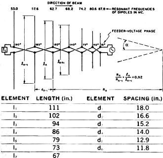
Fig. 3 - Log-periodic dipole array for low-band v.h.f. TV.
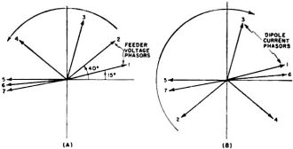
Fig. 4 - Feeder voltage and dipole current phasors illustrating
the effect of transposition of the feeder that is used.
The manner in which the interconnection of several dipoles of different length
can overcome the problem of impedance variation can best be understood by considering
the antenna to be operating as a transmitter. A basic result of antenna theory states
that the input impedance and radiation patterns of an antenna are the same for transmitting
and receiving. In the transmitting case, a generator is connected to the feedpoint
as shown in Fig. 3. Let us suppose that the frequency of the generator is such that
l1/λ = 0.5 where l1 is the length of
the longest dipole. The dipoles near the feedpoint will have considerably smaller
values of l/λ and Fig. 1 shows the input impedance of these dipoles to be
primarily a high reactance. Little energy will be transferred to these dipoles from
the feedline. However, as the wave traveling along the feeder encounters longer
dipoles, more and more energy will be transferred. One secret of a successful log-periodic
design is to insure that most of the energy is coupled into the dipoles before reaching
the end of the feeder. The termination at the last dipole, Zl,
can be important in this regard, particularly for an antenna containing only a few
dipoles. It is preferable to use a reactive load across the longest dipole since
any resistive component will absorb power and reduce the antenna gain. This load
may take the form of an open- or shorted-stub, sometimes in conjunction with a small
capacitor.
The several dipoles which absorb the greater power from the feeder are often
called the "active region." Consideration will be given in the next section to the
manner in which the currents in these dipoles can be made to radiate a highly directive
beam. But now consider what happens when the frequency is changed. In particular
when the next shorter dipole corresponds to l/λ = 0.5, the active
region has simply moved up the feeder by one dipole spacing. The input impedance
at the front of the active region is the same as before and the feeder plus shorter
dipoles between the active region and the feedpoint all have the same or approximately
the same wavelength dimensions as before. Hence the input impedance at this higher
frequency will be the same as at the lowest frequency. Since the dimensions of the
active region are the same in wavelengths, the radiation pattern produced is also
unchanged.
Although the above considerations of scaling indicate that the performance characteristics
of the antenna will repeat at any two frequencies related by the scale factor for
adjacent dipoles, there is no guarantee that the performance will remain constant
between these frequencies. This must be accomplished by proper choice of scale factor,
depending upon the bandwidth of the individual dipoles in the array. For dipoles
with l/d in the range from 300 down, scale factors as low as 0.9 have proved
satisfactory. When scale factor and dipole bandwidth are properly related, then
the active region moves smoothly from dipole to dipole as frequency changes and
variations in antenna performance over an extremely wide frequency band are very
small.
Achieving Unidirectional Patterns
Although a smoothly moving active region is very important in achieving frequency-independent
performance, there are other important considerations as well. The single-lobe radiation
pattern which has a high ratio of front -to-back response requires that several
dipoles be interconnected in the proper manner. Consider the transmitting case once
again. The generator connected to the input terminals of the antenna launches a
traveling wave on the feeder. The voltage on the feeder undergoes a phase delay
as an observer moves away from the feedpoint. The phase shift between dipoles is
increased above the value obtained on an unloaded feeder because of the additional
capacitive reactance which the short dipoles present across the line. Thus, although
the spacing between dipoles in the active region usually corresponds to less than
60 electrical degrees, the feeder voltage phase shift is more nearly 90 degrees.
For determining the pattern of the array, it is the dipole currents which are
of prime importance. The transposition of feeder conductors between adjacent dipoles
introduces an additional 180 degrees of phase shift between dipoles as compared
to using a straight feeder. The combination of these effects is to produce a phase
delay in the dipole currents which is toward the feedpoint of the array rather than
away from it. As a result, the direction of maximum radiation ( as a transmitting
antenna) and maximum response (as a receiving antenna) is along the axis of the
array in the direction of the feedpoint. This phenomenon is often called "backfire"
radiation to distinguish it from the more conventional "end-fire" antennas, such
as multiple-element yagis. Yagis have maximum response off the end which is farthest
removed from the feedpoint.
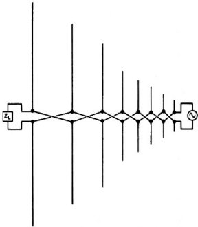
Fig. 5 - Adaptation of array for moderate gain on two bands.
Note the use of the two groups of antenna elements in array.
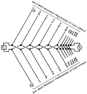
Fig. 6 - An all-channel antenna using half-wave dipoles for low
v.h.f. band and 3/2-wave dipoles for high v.h.f. and u.h.f. bands.
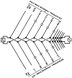
Fig. 7 - All-channel antenna using capacitor-loaded dipoles.
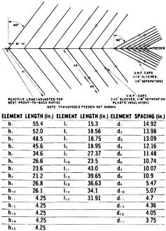
Fig. 8 - An all-channel, 15-element antenna using capacitor-loaded
dipoles. Capacitance and load values were determined empirically for best performance
during original design work.
The manner in which the "backfire" phasing of the dipoles is achieved is illustrated
in Fig. 4 by the arrows labeled "feeder voltage phasors" and "dipole current phasors."
The data shown in Fig. 3 for feeder voltage phases is for a frequency near the center
of the low v.h.f. TV band so that the active region is located at the intermediate-length
dipoles. The feeder voltage phases at the dipoles are characteristic of a wave traveling
away from the generator, i.e., phase increasing toward the left. This is shown in
Fig. 4A by the rotation of the phasors in a counterclockwise direction. Due to the
transposition of the feeder between adjacent dipoles, the dipole currents in alternate
dipoles have a phase which is advanced (or retarded) by approximately 180 degrees.
Reversing the direction of alternate phasors, as shown in Fig. 4B, the direction
of phase progression in the dipole currents is opposite to that of the feeder voltage.
An important feature of backfire phasing is that the radiation is directed away
from the longer dipoles and the result is a high front-to-back ratio. To preserve
the high front-to-back ratio it is necessary to observe a minimum feeder length
of approximately one-third to one-half the maximum wavelength. Minimum front-to-back
size for a backfire antenna with a good front-to-back ratio at channel 2 is, therefore,
about 60 inches.
Multiband Operation
Although the combination of tapered dipole lengths and spacings plus backfire
phasing is ideal for continuous coverage of an extremely wide band, the frequency
allocations for television do not call for this type of operation. In fact, for
an all-channel antenna, it is necessary to cover three separate frequency bands,
54-88, 174-216, and 470-890 mc. There are several approaches to adapting the above
principles for this type of intermittent coverage, however, and we shall consider
briefly the advantages and disadvantages of some of them. Of course, it would be
possible to build a log-periodic dipole array which would cover the entire band
from 54 to 890mc. even though this represents a frequency span of over 16 to 1.
The disadvantage to this approach is that many dipoles would be required and the
total length of the feeder would be rather large even for achieving moderate antenna
gain. It was demonstrated early in the work on log-periodic dipole antennas that
the dipoles which were resonant at frequencies somewhat removed from the bands which
were to be covered could be removed from the antenna without adversely affecting
the performance in these bands. While it is true that this will eliminate several
dipoles and thereby shorten the required feeder, as shown in Fig. 5, the gain remains
relatively constant for all frequencies in the desired bands. This may produce satisfactory
reception in some locations, but generally the properties of wave propagation with
increasing frequency make it desirable to have larger gain on the upper frequency
bands.
The dipole impedance characteristics shown in Fig. 1 suggest a way in which each
dipole on the antenna can be made to operate effectively at more than one frequency.
Since the formation of the active region is primarily dependent upon the impedance
properties of the dipoles, it is reasonable to expect that an active region could
be formed in the vicinity of dipoles which are three-half-wavelengths long. As a
matter of fact, even higher-order resonances which occur at other odd integer multiples
of a half-wavelength could be used for this purpose. In order to achieve an active
region which moved smoothly with frequency, only an appropriate adjustment in the
spacing between dipoles was required; the higher the order of the resonances, the
closer the spacing.
Inspection of the patterns of Fig. 2 reveals another problem with operating in
the higher-order resonances. Note that the pattern of a linear dipole which is three-half-wavelengths
long has six distinct lobes rather than two. Considering the transmitting case once
again, it is easy to see that the power radiated in the side lobes is wasted. The
side lobes can be greatly reduced by shaping the dipole. The simplest configuration
is a V-dipole made by tilting the dipole halves toward one another. The combination
of V-dipoles in a driven array with backfire phasing can be made to have no observable
side lobes and a front-to-back ratio greater than 20 decibels. Since the dipole
is larger in wavelength when used at the higher resonances, the beams produced are
much narrower, resulting in the increased gain which is desired in the higher frequency
bands.
Fig. 6 shows one way in which the higher modes can be utilized in an all-channel
antenna. In this example 3/2-wave dipoles are used throughout the high v.h.f. and
u.h.f. bands. Since the maximum theoretical bandwidth of a 3/2-wave antenna is 3
to 1, further modification of the dipoles is required. The desired result is achieved
through the reactance-loading discussed in the following section.
Reactance-loaded Dipoles
Consideration of the resonances of the dipoles shown in Fig. 6 suggests a way
in which performance of the antenna might be improved, especially in the high v.h.f.
band. Note that the 3/2-wave resonances of several of the dipoles fall at frequencies
outside the 174-216-mc. band. Hence, although these dipoles are required on the
antenna to adequately cover the 54-88 mc. band, they are not contributing effectively
toward achieving the higher gain which is desired in the upper v.h.f. band.
In order to force more of the dipoles to resonate within the 174-216-mc. band,
a way is needed to cause the ratio of first to second resonance frequencies to depart
from the customary value of 3. Recent research has shown that proper placement of
a lumped reactance along the dipole arms can be made to produce the desired shift.
When a capacitor is inserted in the dipole, the frequency variation in the reactance
produces a different effect at the second resonance than at the first. Ratios as
low as 2 have been achieved in this way. The antenna shown in Fig. 7 illustrates
how more of the capacitance-loaded dipoles can be made to resonate in the higher
v.h.f. band. The more active dipoles, the greater the gain. An additional benefit
of the capacitor is to cause the resonances to occur at longer dipole lengths. Greater
length produces greater gain.
Reactance loading can be used to achieve yet another result. The directivity
of 5/2-wave dipoles is greater than 3/2 -wave and that of 7/2-wave greater than
5/2-wave, etc. Hence it would be desirable to use these longer dipoles to cover
u.h.f. frequencies. Since the wavelength is so much shorter at u.h.f., operating
in even these higher resonances does not require an inordinately long dipole. However,
the tilt of the dipoles for the higher modes must be increased to maintain low side
lobes. A section of dipoles which operates on the higher modes for u.h.f. is easily
added to the front of a section designed to operate in no higher than 3/2-wave resonance
at v.h.f. and can, in fact, be integrated to enhance the v.h.f. performance.
To achieve this, however, an adaptation of the linear dipoles is required. Ordinarily
the longer u.h.f. dipoles would resonate at frequencies in or near the v.h.f. band.
This would prevent the less sharply vee'd dipoles from receiving any energy from
the generator (considering the transmitting case). It is possible to effectively
disconnect the larger dipoles from the feeder at v.h.f. frequencies by once again
inserting a capacitor in the dipole. The capacitor (formed merely by a break in
the element) is designed to have sufficiently high reactance to decouple the sections
of the dipole at v.h.f. frequencies and yet low enough reactance to couple at u.h.f.
frequencies. The outboard portion resonates above the upper end of one of the v.h.f.
bands and therefore will enhance the v.h.f. gain in the manner of a conventional
parasitic element. Fig. 8 shows an antenna which makes use of these latter modifications,
along with radiation patterns (Fig. 9) which have been measured in each one of the
three bands. The reduction in beamwidth illustrates the increased directivity and
gain which is achieved by operating in the higher modes.
Installation of All -Channel Antennas
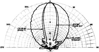
Fig. 9 - Horizontal directivity patterns of fifteen-element antenna.
Although the use of a well-designed, all-channel antenna will alleviate the difficulties
often encountered in a multiple antenna installation, there are still several precautions
which should be observed to insure realization of the full performance potential
of the antenna. Experience with v.h.f. installation is no guarantee of equal performance
on u.h.f. since the higher frequencies behave quite differently. The first rule
of a good u.h.f. installation is to use best quality, low-loss lead-in. This is
essential for u.h.f. but will also increase the v.h.f. signal level at the set.
Encapsulated lead-in is recommended for general use. Low-loss stand-offs which hold
the lead-in away from any metal are best for u.h.f. In those cases where electrical
interference is a problem, a low-loss shielded twin-lead should be used.
If amplification is required on an all-channel antenna, be sure to use an all-channel
amplifier. The u.h.f. signals are generally attenuated severely by a v.h.f. amplifier
and vice versa. If only u.h.f. or only v.h.f. amplification is desired, the amplifier
can be used on the output of the signal splitter.
The narrow patterns of the all-channel antennas require careful orientation of
the antenna toward the station. If stations are located in more than one direction,
a good quality continuous-turning rotator is a wise investment.
With the rapid growth of u.h.f. and color television with their more stringent
performance requirements, most antenna installations which are more than three years
old are probably not adequate. The new all-channel antennas provide a good answer
to the question of how to improve the reception of today's television programming.
Posted August 15, 2022
|