Japanese Technology - Bidding for World Leadership in Solid State Microwave
Gear |
|
The December 13, 1965 issue of Electronics magazine was largely dedicated to assessing Japan's status in the electronics industry. Japan, with the help of the United States, made a remarkable recovery from defeat during World War II to have become an emerging power in electronics. "Made in Japan" labels on products had transformed from being the butt of jokes because of pre-war low quality products to representing assurance of low cost, high functionality and high value products. It still does to this day. The Japanese people have worked hard to acquire the world's respect as smart innovators and hard workers, and have been sure to maintain manufacturing bases within their borders. When you read this article, be prepared for a few dated terms like a "Kita" diode, having gigahertz (GHz) presented as gigacycles (Gc), decibels abbreviated as "db" rather than "dB," intermediate frequency given as "i-f" instead of "IF," and "polyiron" which if you look it up, nowadays refers to vitamin supplements rather than iron metal alloys. Japanese Technology - Bidding for World Leadership in Solid State Microwave Gear
The Author Isao Someya is chief of the director's office at the Electrical Communications Laboratory in charge of planning. He is a 1938 graduate of Tokyo University and earned his doctorate degree from the university in 1951. With problems uniquely suited to solution by microwave, the Japanese are making big advances in solid state equipment using such components as the tunnel diode, Kita diode, hyperabrupt diode and mesa transistor By Isao Someya Electrical Communication Laboratory Nippon Telegraph and Public Corp. Japan has many of the problems that microwave is best-suited to solve - communications needs of a dense population (about half that of the United States squeezed into an area smaller than Montana), a combination of mountainous terrain and narrow streets that make coaxial cable difficult to install and maintain, and expensive and limited natural power. Japan also had an "advantage" - a chance to start fresh after 80% of its telephone service had been destroyed during World War II. For these reasons, the country chose microwave and today has the densest system in the world. Japan's first solid state microwave system went into operation in 1962, an 11-gigacycle system that connected television studios to telephone exchanges a short distance away. The system required only 10% as much power as would a comparable tube setup, and construction costs were halved. Because of these savings, Japan developed solid state systems and today boasts that her solid state microwave gear is as good as any in the world. Although Japanese engineers borrow heavily from United States technology, they have made significant contributions in the microwave field, primarily with the application of Japanese-developed components such as the tunnel diode and the Kita diode. Since there are no military programs to prime the research pump in Japan, most of the development has been done at the Electrical Communication Laboratory of the government-owned Nippon Telegraph and Telephone Public Corporation. Its laboratory is comparable, in a modest way, to the Bell Telephone Laboratories. More recently, development work of this type has also been carried on in the research laboratories of a few private companies; the Nippon Electric Co., Fujitsu Ltd., Hitachi Ltd., Mitsubishi Electric Corp. and Toshiba (Tokyo Shibaura Electric Corp.).
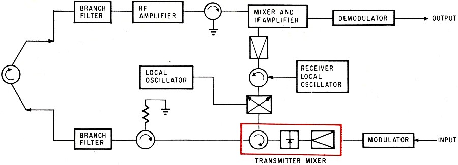
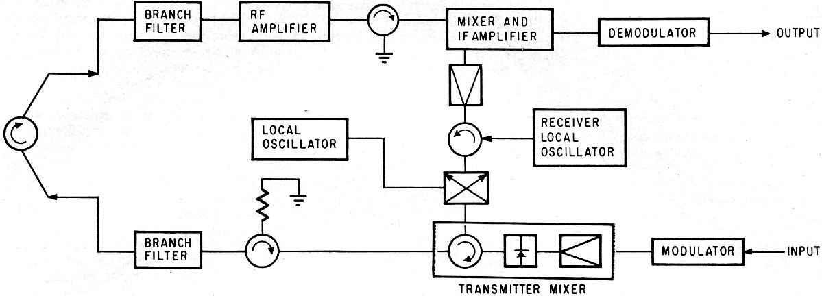
New baseband repeater for solid state 2 Gc system. Transmitter-frequency mixer (color) supplies 300 mw output.
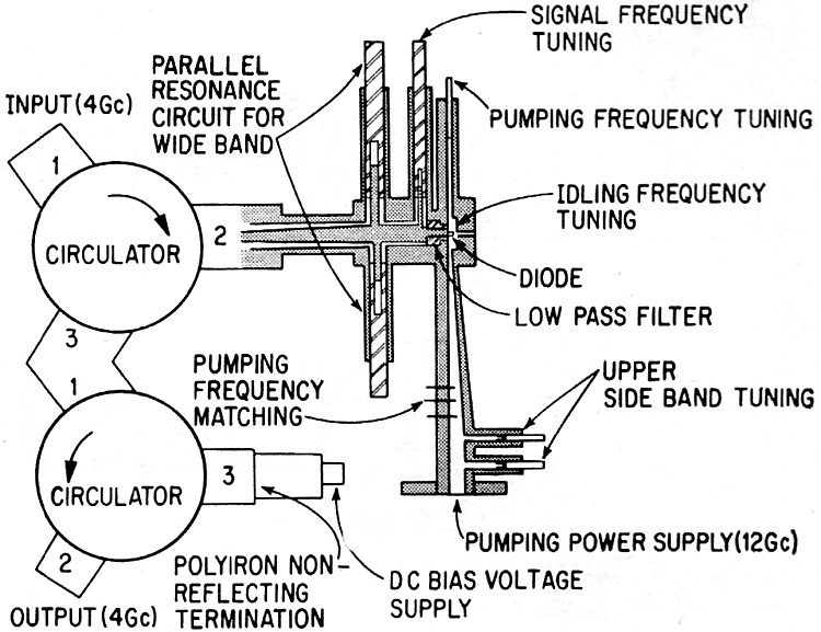
In parametric amplifier for 4-Gc system, d-c biasing voltage is fed through the circulator and polyiron non-reflecting termination. Pump power is supplied by a tripler which multiplies the output of the transmitter local oscillator.
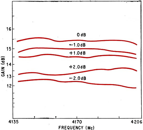
When pump power changes, variation of gain in parametric amplifier for 4-Gc system is small.
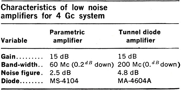
Characteristics of low noise amplifiers for 4 Gc system.
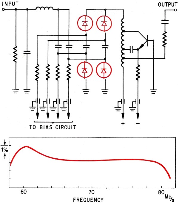
Frequency modulator (top), with four abrupt junction diodes (shown in color) in tuning circuit has linear output. Linearity, bottom, is within 1% over range of 70 Mc ±8.
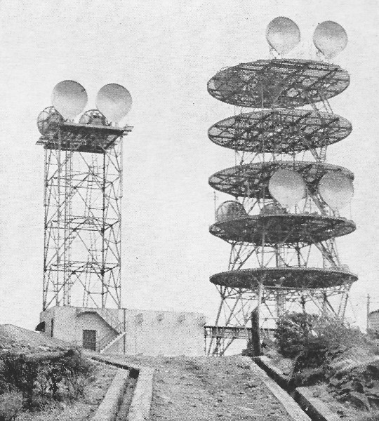
Microwave repeater stations, like this one at Futago Yama, dot the hilltops of the Japanese countryside. Inside the building is a heterodyne repeater.
Block diagram of local oscillator in broadband repeater for 6 Gc system has a crystal oscillator, transistor amplifiers and multipliers. Narrow bandpass filter, composed of two stages of cavity resonators operating in the H021 mode, reduces undesired harmonics and noise.
Switching circuit with Kita diodes has transition time of 15 to 20 nanoseconds for break and 40 nanoseconds for restoration. That is more than adequate, even for high-speed data transmission of 1,000 to 2,000 bands for which a transition time of 40 microseconds is required.
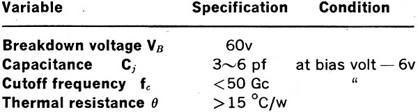
Specifications for varactor diode in high power multiplier. Once a development is perfected, the Electrical Communication Laboratory (ECL) turns the design over to one or more manufacturers. The Japanese success in competing in the international market is evident in the sales of microwave equipment to the governments of Mexico, Taiwan, and Indonesia. Solid state research in the microwave field in Japan can be traced to 1955 when the concept of the parametric amplifier was proposed independently at ECL. From this proposal came the development of variable capacitance diodes (varactors) and silver-bonded or Kita diodes. Mesa transistors with gain-bandwidth products of several hundred megacycles were developed in 1959. Today in Japan, parametric amplifiers are used mainly in over-the-horizon systems of medium capacity operated by private users such as railroads and utility companies. NTT has used these amplifiers in a 2-Gc over-the-horizon system that connects the southern island of Kyushu to Okinawa. And the applications are increasing as the microwave networks grow. Last March, NTT tested a new all-solid state 2-Gc system. First units of this UF-B4 system are being installed now, and are scheduled to be operating before the end of the year. Designed for short telephone circuits where branching is frequent, the UF-B4 generally uses a baseband repeater (see block diagram above) but can also use a heterodyne repeater for long-distance systems. One of the most interesting parts of the repeater is the transmitter-frequency mixer, which supplies the 300-milliwatt output of the transmitter. A local oscillator of the frequency-multiplier type delivers about one watt to the mixer. In the transmitter converter, a 70 Mc carrier that has been frequency-modulated by the baseband signal is heterodyned against the transmitter's local oscillator to produce the transmitter output signal. Power loss of about 5 decibels in the transmitter mixer accounts for the difference between the one-watt frequency-multiplier output and the 300-milliwatt transmitter output. As a baseband system, the modulator is connected to the last i-f amplifier, which is sometimes called the post-i-f amplifier, so that the signal is amplified to the high level required at the transmitting mixer. When the mixer is to be used as a heterodyne repeater, the output of the receiver main i-f of half the repeater is connected to the last i-f amplifier of the transmitter of the other half. In this configuration, the receiver demodulators and transmitter modulators are not used. The power consumption of a repeater in this 2-Gc system is about 100 watts. The standard repeating span is about 31 miles. If the span loss is large, NTT inserts a tunnel-diode amplifier with a gain of 15 db and a noise figure of 5 db on the front-end of the receiver. In the 70 Mc modulator, hyperabrupt junction diodes are the modulating elements. Low-Noise Amplifiers While one section of ECL is designing systems, another section works on components. One major area of research has been in low-noise amplifiers. At present, the laboratory considers only the parametric amplifier, operating at room temperature, and tunnel-diode amplifiers practical for broadband microwave systems. Maser and parametric amplifiers, which operate at the temperature of liquid helium, are so expensive and difficult to maintain that NTT considers them unsuitable for first-stage amplifiers of broadband systems. So far in NTT's networks, parametric amplifiers have been used commercially only in the over-the-horizon system between Kyushu and Okinawa. The amplifiers are placed in the front ends of the receiver for this link's two operating bands: 900 Mc for television and 2-Gc for multichannel telephone transmission. A similar amplifier has been designed for a 4 Gc broadband system (see figure next page) that can handle 960 telephone channels. The doc biasing voltage, which is applied to the varactor diode, is fed through the circulator and polyiron non-reflecting termination. Coaxial lines are tuned by inserting dielectric plungers. Pump power for the amplifier, 10 to 20 milliwatts at 12 Gc, is supplied by a tripler which multiplies the output of the transmitter local oscillator. As pump power changes, variations in gain characteristics of the amplifier are small (see p. 103). Because of the design, automatic control of the pump power is unnecessary; this simplification is made possible primarily by the characteristics of the device: an optimum self-bias voltage for the diodes and suitable detuning of the resonance circuit. These characteristics eliminate variations in the bandpass characteristics. In 1963, research started on an 11-Gc parametric amplifier built with silver-bonded diodes. These diodes are a unique Japanese development, devised by Shoichiro Kita at ECL in 1955. Many types of these devices are now made in Japan for parametric amplifiers, microwave switches, transmitter converters for repeaters and i-f limiters. Because of its Kita diodes, the 11-Gc amplifier had a very low noise figure: 3 db measured for sideband reception at room temperature and 0.7 db at 85°. The other low-noise amplifier favored by the Japanese is a tunnel-diode type. This amplifier is not suitable for systems operating with relatively high input lines, because its saturation level is low. This restriction can be removed if tunnel diodes with high negative conductance are chosen. For example, in the receiver of a 4-Gc broadband system, a tunnel-diode amplifier has a noise figure only slightly worse than a parametric amplifier. But it has one big advantage: it can amplify microwaves without requiring pump power. Frequency Multipliers When the Japanese became acquainted with variable capacitance diodes or varactors, they began using them in frequency multipliers. NTT uses such a frequency multiplier as a local oscillator when the required output power of the oscillator is low and the frequency is 6 Gc or less. Under these operating conditions, the solid state multiplier has a higher efficiency (defined as the ratio of microwave output to the doc power input) than the conventional klystron oscillator. In addition, NTT has found that the longer life of a diode and the elimination of complicated automatic frequency control circuits simplify maintenance. In the SF-U2 system - NTT's second-generation 6-Gc system - only the local oscillator is solid state. Its output is only 20 dbm (20 db above 1 milliwatt or 100 milliwatts). But in the newest 6-Gc system, the SF-U3 - scheduled for field test in 1966 and for installation in 1967 - all vacuum tubes are replaced by transistors. The local oscillator in this new system (see block diagram p. 104) has a crystal oscillator, transistor amplifiers and multipliers. Operating at a frequency between 55 and 59 Mc, the crystal oscillator is an overtone type. The input to the frequency multiplier has a frequency-modulated noise component. Because its frequency deviation is multiplied by a factor of 108, parasitic oscillations have to be suppressed and noise reduced in the crystal oscillator and power amplifiers that follow. To reduce undesired harmonics and noise, a narrow bandpass filter - composed of two stages of cavity resonators operating in the H021 mode - has been inserted in the output of the multiplier. The loaded Q of the filter is about 8,000 and its insertion loss is about 2 db. ECL also has developed a new frequency multiplier for the new all-solid state 4-Gc system. In this multiplier, the overtone crystal oscillates at 114 Mc, This signal is amplified to about 30 watts before two tripler stages increase the frequency to 1,025 Mc. The last two multiplier stages are doublers. They are made with a special varactor diode, the ECL 1242, which has an output of 2.5 watts at 4 Gc (see table p. 105 for its characteristics). Thus, the power range of the multiplier varies from an input of 30 watts at 114 Mc to an output of 2.5 watts at 4.1 Gc. Improvements in solid state i-f amplifiers have made it possible to design better solid state repeaters. A solid state i-f amplifier was used first in 1961 in the first-generation 11-Gc system. Its bandwidth was large enough to amplify 600 telephone channels. Better transistors and transistor circuitry boosted this capability to 1,800 telephone channels and such an amplifier is now in production. ECL also has almost completed work on an improved amplifier that can handle 2,700 telephone channels - more than quadrupling capacity in 4 years. Low-Noise Parametric Amplifier A key performance characteristic is output voltage. The output voltage of the i-f amplifier, designed for the repeater of the new solid state 4-Gc system, is 90 volts into a load of 500 ohms in parallel with 10 picofarads. This is a desirable performance for a heterodyne-type repeater, which requires a large i-f amplifier output supplied to the transmitter frequency mixer. In addition, a large i-f input decreases the microwave loss between the input of the local oscillator and the output of the transmitter frequency mixer. The new i-f amplifier has a frequency characteristic which deviates less than 0.2 db at 70 Mc + 10 Mc. Another component that has made an important contribution to microwave technology in Japan is the hyperabrupt junction diode, which has made possible solid state frequency modulators. The useful characteristic of a hyperabrupt junction diode is the value of n in the equation for junction capacitance: Cj = (Ck)/(φ - V)n where Cj = junction capacity Ck = a constant V = bias voltage supplied to diode φ = contact potential Usually, n is larger than 1/2 and sometimes is as large as 5 or 6. If a diode with an n value of about 2 is placed in the tuning circuit of the modulating oscillator and its bias voltage is controlled by the input signal, its linearity is good enough so the oscillator can modulate a super multi-channel signal. Under these conditions, the variation of differential modulation is less than 1% in the range of 70 Mc + 4 Mc. Sensitivity is more than 10 Mc per volt. Also, when several diodes are connected in parallel and are given different bias voltages to compensate for the characteristics of each, linearity can be improved to cover a broader range of frequency deviation. One modulator designed this way used 4 hyperabrupt junction diodes (see figure p. 104) and its variation of differential modulation was less than 1% in the range of 70 Mc ± 8 Mc (see figure below circuit on p. 104). Solid State Switching Traditionally, the reed relay has been used for switching an r-f channel to a protection channel when there is equipment failure or severe fading. The transition time of these mechanical devices is 1 to 2 milliseconds. Since this time is barely satisfactory for the transmission of 50-band telegraphy, it is clearly unsatisfactory for high-speed data transmission. Therefore, ECL has developed a solid state unit, using Kita diodes, for the 11-Gc system and the unit can be used in the new 15 Gc system, too. The actual design goes back to 1959, even though it has been used only recently. When such a switching circuit (see figure above) is used in the receiving side of a broadband telephone system, the distortion introduced by the diodes which are positively biased, must be kept small. The impedance ratio of reverse-biased diodes to positive-biased diodes determines the quantity of cross talk between switched channels. The insertion loss of this circuit is less than 0.6 db. The transition time is about 15 to 20 nanoseconds for break, 40 nanoseconds for restoration. These times, which include the operation times of the driving circuits, are more than adequate because the transmission of high-speed (1,000 to 2,000 band) data requires a transition time of about 40 microseconds. To extend solid state in microwave, researchers in Japan are concentrating on developing power transistors and varactor diodes that can handle the higher frequencies at higher powers. The biggest obstacle is not system design, but lack of understanding of the diffusion technology for producing such devices.
Posted July 18, 2019 |
|
")