September 1969 Electronics Illustrated
 Table
of Contents Table
of Contents
Wax nostalgic about and learn from the history
of early electronics. See articles from Electronics Illustrated, published May 1958
- November 1972. All copyrights hereby acknowledged.
|
As with many
areas of electronics communications, much of both the initial and continued
research in atmospheric scattering of electromagnetic signals was/is done by
amateur radio operators. The phenomenon is routinely used for accomplishing
long distance communications (DX, in Ham terms) by exploiting the reflection
property of ionized layers when radio signals impinge at a certain angle. The
portion of the signal that returns to the transmitter location, when monitored,
can provide information to the sender about the height, distance, and frequency
range of the reflecting atmospheric layer. Some of the first indications of
backscattering were noticed by radar operators who would receive echo returns
from "phantom" targets that were really atmospheric reflections.
They're Taking the Guesswork out of Scatter Communications
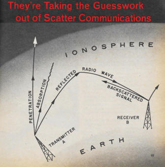
To get a good signal into a target area international short-wave
broadcasters now are probing the ionosphere.
By Stanley Leinwoll
International broadcasters located in the United States are developing a
system based on the principles of radar that will boost the signals aimed into
target areas without requiring increased power or antenna gain. The system,
called backscatter sounding, is expected to be operational within a year. If
successful it could revolutionize broadcasting techniques on both short-wave
and amateur bands.
How It Works
Radio waves striking objects on or above the earth are reflected and scattered
in all directions. A small portion of this reflected energy always returns to
its source. By measuring the time between the transmission of the energy and
its return to the point of origin, accurate determination of the reflecting
objects distance from the transmitter can be made.
We know radio waves travel at the speed of light - 186,000 mi. per second.
A delay of a microsecond between the time a radio wave is transmitted and the
time it's received back at the transmitter corresponds to a round trip (984
ft.) over a path 492 ft. long. All radar measurements are based on this principle.
Most radar devices, however, operate at frequencies of 1,000 mc or more because
short wavelengths give a more accurate determination of the size and shape of
physical objects.
Shortly after World War II it was discovered that short radio waves (between
3 and 30 mc) display radar-like characteristics. These properties help to reveal
information about a signal as well as valuable information about the ionosphere.
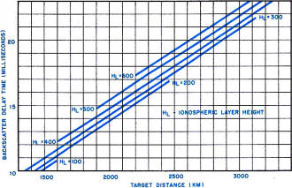
Fig. 1 - Nomograph shows relationship of backscatter time
to target distance. Height of Ionosphere (up to 300 mi.) depends on amount
of solar activity.
Long-distance short-wave communication is possible because there exists in
the atmosphere a series of electrified layers collectively referred to as the
ionosphere. The ionosphere is capable of reflecting radio waves in the high-frequency
(3-30 mc) portion of the RF spectrum. However, the ionized gases making up the
ionosphere change from day to night, from season to season and over an 11-year
cycle dependent on the number of sunspots.
A high-frequency radio wave entering the ionosphere will either be absorbed,
be reflected back to earth or be lost in outer space. Reflection back to earth
depends on the amount of ionization in the layers, the frequency of the radio
signal and the angle at which the wave strikes a particular layer. Most radio
energy returning to earth is reflected by the earth back to the ionosphere,
where it is again reflected to a distant point. These sky waves make communication
over great distances possible.
Backscatter Technique
Because of irregularities on the surface of the earth, a small portion of
the energy striking it at some point will be scattered in all directions and
even scattered back toward the transmitter. (Hence, the term backscatter.) By
setting up a directional antenna and a receiver that feeds its output into an
oscilloscope the backscattered signal can be monitored and analyzed right in
the vicinity of the transmitter.

Engineer for Radio Free Europe compiles detailed charts as he listens
to international short-wave band. Effort is made to Improve RFE's signal. UPI
Photo
If the transmitter should send a series of pulses at different frequencies,
say beginning at 3 mc and sweeping up at predetermined intervals to 30 mc, a
receiver monitoring these pulses will show just what frequencies are being backscattered.
Some of the signals will be absorbed by the ionosphere, some will penetrate
it and some will be propagated. Backscatter sounding tells the broadcaster which
frequencies are being propagated by the ionosphere and consequently which frequencies
can be used for communication to a specific area of the world.
In addition, when the pulses are viewed on a scope, the time delay can be
calculated. The time delay between the transmitted pulse and received echo gives
the approximate location of the point of reception. This is illustrated in Fig
1. If a scope shows a delay time of 20 milliseconds at a particular frequency,
we can arrive at our target's distance by estimating the height of the ionosphere
(HL). In general, 300 kilometers is a reasonable assumption and the chart gives
us a target distance of about 2,900 kilometers. Since no energy has been returned
from a closer location it follows that the target distance was about 2,900 kilometers
(or 1828 miles).
Radio Free Europe. The backscatter sounding system currently under test by
Radio Free Europe is more sophisticated than the technique described above.
It consists of a high-gain curtain antenna for transmitting and a frequency-shift
pulse keyer at the input. This device shifts the carrier frequency of a transmitter
for short periods of time while pulses of energy are sent out. A receiver and
antenna system are tuned in step with the shifted carrier. The antenna consists
of nine vertically-stacked cubicle-quad elements mounted on a 108-meter tower.
It operates in the 11.8-, 15.3-, and 17.8-mc international short-wave bands
and can be adjusted so that the vertical-radiation angle changes to receive
maximum energy at different angles (from 3.5 to 22.5 degrees).
Changing the optimum receiving angle is important because it helps determine
which receiving mode is producing the strongest signal at a given frequency.
International broadcasters such as Radio Free Europe operate on a fixed frequency
schedule and cannot utilize backscatter equipment to determine which band is
propagating best in order to make an assignment in that band. Instead, they
have to determine which angle is producing the strongest signal on a particular
frequency and then adjust the transmitting antenna to fire at that angle; this
way a better signal is propagated into the target area.
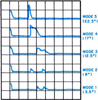
Fig. 2 - RFE backscatter depends on finding best angle propagation
of signal at a given frequency. Distance increases as angle decreases.
The technique of adjusting your radiation angle is called slewing. RFE has
a number of vertically-slewable antennas and is planning to construct others
to take maximum advantage of its backscatter equipment. Fig. 2 shows what a
typical display looks like. Mode I corresponds to the lowest transmitting angle
and Modes 2 to 5 refer to increasing vertical angles. As expected, Fig. 2 shows
that as the transmitting angle is decreased, the backscattering distance increases.
Modes 1 and 2 show energy returning from two distinct zones; this is probably
caused by reflection of the signal from different layers of the ionosphere.
This situation frequently occurs during daylight hours.
Amateur Applications
Backscatter sounding promises to lend itself even more to amateur radio than
to international broadcasting because the amateur is not limited to a fixed
frequency schedule. To understand the great potential for an amateur backscatter
network consider the display shown in Fig. 3. Instead of making soundings at
different radiation angles on a single frequency, we switch to soundings for
the different ham bands (i.e., 40, 20, 15, 10 and 6 meters).
The first pulse is the one received directly from the transmitter. The 40-meter
trace shows two other pulses, one relatively close to the transmitter, the second
about twice as far away. This is probably due to a second-hop transmission.
Because of signal strength. the signal has returned to the ionosphere a second
time, been reflected by the earth a second time, and both backscattered signals
have been picked up at the receiver.
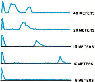
Fig. 3 - Backscatter display for amateur bands. First
pulse is from transmitter; echoes indicate distance of transmission (greater
with higher frequency).
Succeeding traces show that as frequency is increased, the skip also increases-until
at 6 meters we find there is no trace at all. This means that at 6 meters the
ionosphere was not propagating and the radio energy was probably penetrating
into outer space. Communication on all the other bands was possible, however.
Fig. 3 emphasizes the significance backscatter sounding has for the radio
amateur. Here is a method by which instantaneous information on skip in various
bands can be obtained. One might envision a network of backscatter sounding
stations run by the ARRL and located at various points in the United States.
Each such station would have a horizontally-rotatable backscatter array so that
soundings could be made in all directions.
Periodic announcements could be made over official ARRL station W1AW, as
well as over regional stations, giving the best bands and the approximate skip
distances on all bands. By listening to these stations hams would know which
bands to operate in. Such forecasts would help CBers and SWLs too.
Posted July 28, 2020
|