Reader's Digest Model 800-XR AM/FM Radio + 8-Track Tape Player |
|
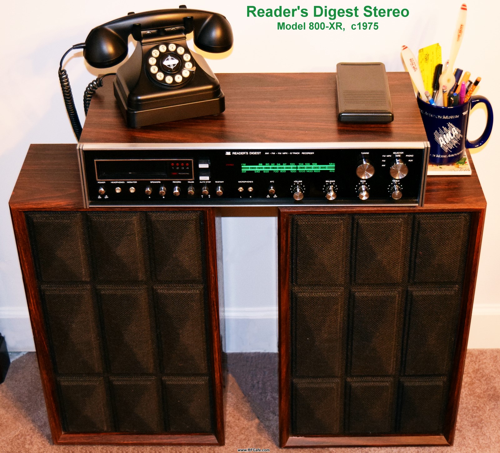
Reader's Digest Model 800-XR Stereo System. AM/FM radio, 8-track tape recorder/player, auxiliary input and phonograph input.
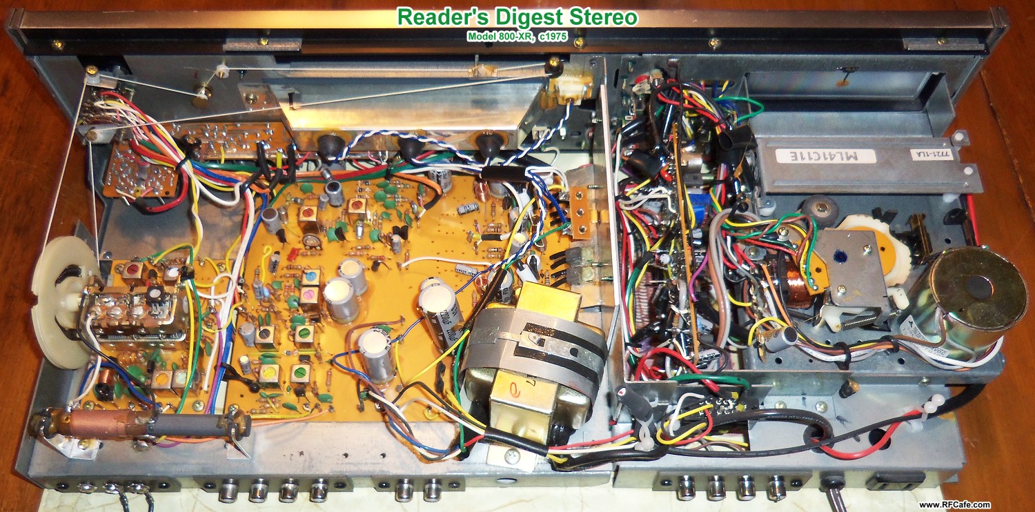
Chassis bottom.
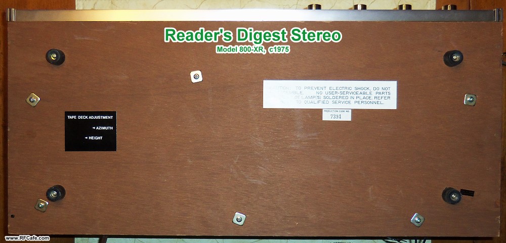
Rear panel.
Circuit board component side. The sight of dial cord gives me goose bumps ;-)
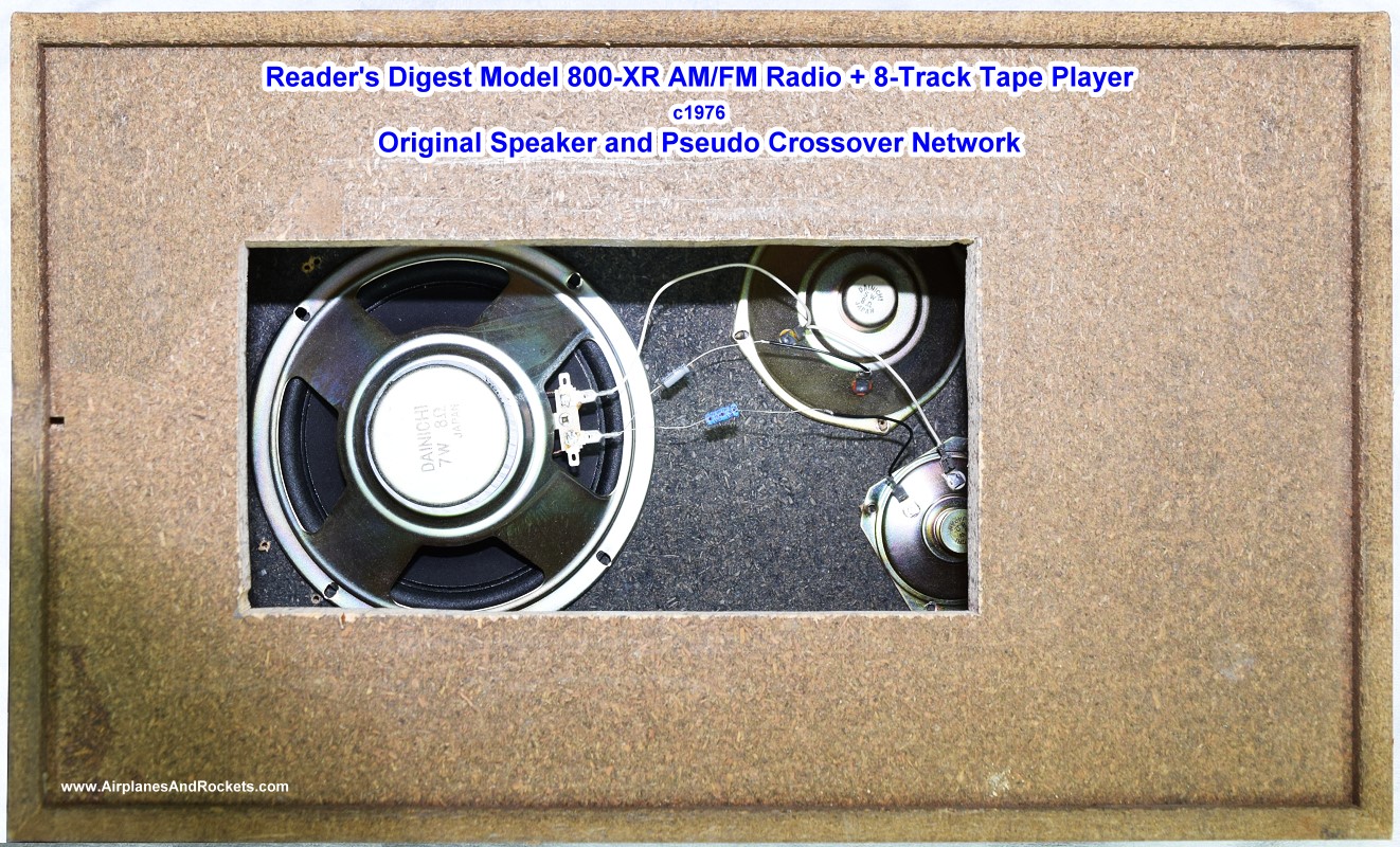
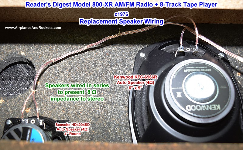
Circuit board trace side. Speaker Modification (July 2018) The original speakers on my Reader's Digest 800-XR stereo system sounded OK, but they sounded crackly at some frequencies even at normal volume level, so I decided to replace the speakers with something more modern. Not wanting to spend a lot of money on speakers and a crossover network, I opted for a set of car speakers with built-in crossovers. Since car speakers have a 4 Ω impedance and the stereo wants 8 Ω, I wired the two new speakers in series.
Hole cut in back of speaker for access. Note the lame crossover network consisting of a couple series capacitors.
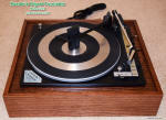
Replacement speakers are automotive type with built-in crossovers. C-141 Turntable (May 2017)
Here is a little documentation on the restoration of the Reader's Digest C-141 Turntable that came as part of this set. It was manufactured by CSR - not high end, but good enough. While photographing the General Electric 7-4305c clock radio that I posted last week, it occurred to me that I had never posted anything on my Reader's Digest 800-XR stereo system. It is another of my had-since-a-teenager electronic items that still works as well as the day I bought mine in fall of 1975. Self-respecting audiophiles would never admit to having ever owned such a low-end system, but at least at the time it was the best I could afford. The price escapes me, but it was somewhere in the $100 neighborhood. A turntable came with it, but that is long gone now. Since I much prefer listening to over-the-air broadcasts rather than on the Internet, both the AM and FM tuners get a daily workout. A whopping 10 watts per channel stressed the limits of what my parents would tolerate, and it was loud enough to get some good booming bass - something my previous weenie radios could never do. There are no preset buttons, so the dial gets twisted just like it did 40 years ago. The front panel volume potentiometer had gotten a bit scratchy during adjustments (static through the speakers), so just yesterday I squirted some CRC QD™ Contact Cleaner into a small hole in the pot body and rotated the shaft back and forth along its full travel a couple dozen times et voila, no more scratching. If memory serves me correctly, there was also a cassette tape deck version available, but I was already deeply invested in 8-track tapes (maybe a dozen - Beach Boys, Boston, Jim Croce, Heart, to name a few), so that's what I got. We 8-track adopters were routinely chided by the haughty cassette deck owners, but I always liked the ability to move between songs simply by punching the track change button rather than having to fast forward or reverse sometimes for the entire length of the cassette just to get to a different song. This stereo system followed me into the barracks in at Robins AFB. Some scurvy dog broke into my Camaro one night and stole all my 8-tracks. Of course the aforementioned jolly jokers told me it was the best thing that could have happened to me, but I confounded them all by going out and reconstituting my 8-track library. July 2018 Update: Over time, the right channel on the Speaker A output became scratchy and sometimes would drop out completely. There was also an issue with distortion on all outputs when the volume was turned up even a little past normal level. It was finally time to open 'er up at take a look. While having the system disassembled, I went ahead and replaced the speakers inside the enclosures since they, too, were showing signs of age. A signal generator was used to pump a sinewave of various frequencies into the system and then signals were traced through the circuit to locate the problem spot. Cleaning a dirty volume potentiometer (pot) solved the scratchy right channel problem. I cleaned all the accessible pots and switches with spray contact cleaner while twisting the knobs back and forth. While tracing the signal, I noticed that the right channel was lower in amplitude at all frequencies than the left channel for both Speaker A and Speaker B output. Measurements showed amplification factors through the active stages were nearly equal. Schematics were not available, so that made the job difficult. I finally identified a resistor connected between the right channel path and ground about in the middle of the signal path. There was no equivalent resistor for the left channel, so I figured it was selected at the factory to balance channel amplitudes. Fortunately, I have a spare chassis, so I looked at it and verified that its resistor value was a little different, so that pretty much confirms the function. The resistor was removed and a potentiometer was tack soldered in place and it was adjusted until left and right channels were equal amplitude at the outputs. The pot was removed and measured, then a fixed resistor was soldered permanently in place. Finally, I replaced gain-setting resistors to make sure that with the new speakers connected, turning the volume controls all the way up would not create distortion at the output in the test sinewave. The original biasing scheme produced distortion at about half the volume adjustment range (this is not an expensive stereo). Everything is back together and performing very well.
Posted December 14, 2014 |