Module 3 −− Introduction to Circuit Protection, Control, and Measurement
Pages i,
1−1,
1−11,
1−21,
1−31,
1−41,
1−51,
1−61,
1−71,
2−1,
2−11,
1−21,
2−31,
2−41,
3−1,
3−11,
3−21,
3−31,
AI−1,
AII−1,
AIII−1,
IV−1,
Index
| - |
Matter, Energy,
and Direct Current |
| - |
Alternating Current and Transformers |
| - |
Circuit Protection, Control, and Measurement |
| - |
Electrical Conductors, Wiring Techniques,
and Schematic Reading |
| - |
Generators and Motors |
| - |
Electronic Emission, Tubes, and Power Supplies |
| - |
Solid-State Devices and Power Supplies |
| - |
Amplifiers |
| - |
Wave-Generation and Wave-Shaping Circuits |
| - |
Wave Propagation, Transmission Lines, and
Antennas |
| - |
Microwave Principles |
| - |
Modulation Principles |
| - |
Introduction to Number Systems and Logic Circuits |
| - |
- Introduction to Microelectronics |
| - |
Principles of Synchros, Servos, and Gyros |
| - |
Introduction to Test Equipment |
| - |
Radio-Frequency Communications Principles |
| - |
Radar Principles |
| - |
The Technician's Handbook, Master Glossary |
| - |
Test Methods and Practices |
| - |
Introduction to Digital Computers |
| - |
Magnetic Recording |
| - |
Introduction to Fiber Optics |
| Note: Navy Electricity and Electronics Training
Series (NEETS) content is U.S. Navy property in the public domain. |
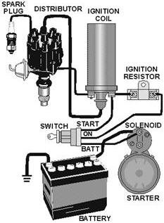
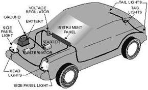
Isometric Diagram - Shows the outline of a ship, airplane, or
piece of equipment. This diagram shows the components and the cable runs between
the components. This diagram is used to locate components in a system.
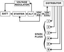
Block Diagram - Shows the components in block form. Block diagrams
are used in conjunction with text material. They are used to present a general description
of a system and its functions.
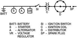
Single-Line Diagram - used for essentially the same purpose
as the block diagram-to show the basic functions of a circuit.
Schematic Diagram - Shows, through graphic symbols, the electrical
connections and functions of a specific circuit arrangement. It is used to trace
the circuit without regard to the physical size, shape, or location of the component
devices or parts. a schematic diagram shows the overall operation of a system. It
is used during troubleshooting to identify possible circuit malfunction locations.
Wiring Diagram - Is a detailed diagram of each circuit installation
showing all wiring, connectors, terminal boards, and the electrical or electronic
components of the circuit. It also identifies the wire-by- wire numbers or color
coding. This diagram must be used in conjunction with a schematic diagram to troubleshoot
a system in order to find the test point for voltage and resistance checks.
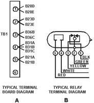
Terminal Diagram - Is used in connecting wiring to terminal
boards, relays, switches, and other
components of a circuit.
Safety - All individuals are responsible for understanding and
complying with safety standards and regulations established to prevent injury to
themselves and others and damage to property and equipment.
Having safe working habits and adhering to safety precautions protects YOU and
YOUR SHIPMATES. Follow safety precautions to the letter. DO NOT TAKE CHANCES. Carelessness
could cost you your life.
Answers to Questions Q1. Through Q18.
A1. To provide the technician with a means to trace the
wires when troubleshooting and repairing electrical and electronic systems.
A2. In the technical manual for the equipment.
A3. Individual cable in a specific circuit.
A4. Wire segment letter.
A5. The conductor connections both "to" and "from."
A6. To prevent electrical shock to the operator in case
there is an electrical short to the frame of the appliance or too.
A7. a pictorial diagram.
A8. An isometric diagram.
A9. Block or single-line diagram.
A10. a schematic diagram.
A11. Between point (3) and the gas gauge tank unit ground.
A12. Only the brake lights.
A13. Wiring diagram.
A14. To find the test points.
A15. Terminal diagram.
A16. Adequate ventilation.
A17. Approved meters or other indicating devices.
A18. By use of a cleaning cloth.
|


