Directional Couplers / Quadrature Hybrid Couplers |
|||||||||||||||||||||||||||
|
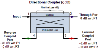
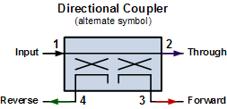
Directional couplers are implemented using a variety of construction techniques (stripline, coaxial, lumped element) and packages (connectorized, solder pins, substrate carrier). What they all have in common is the ability to tap a sample of the input power without significantly affecting the original signal. Generally, for well-designed devices the smaller the portion of the input power that the coupled power port extracts, the less profoundly the input signal is affected. For instance, a 30 dB coupler takes only 0.1% of the input power as a sample to Port 3 and passes the remaining 99.9% out Port 2 (assuming no mainline resistive loss). The opposite extreme is a hybrid 3 dB coupler that evenly divides the input power between Port 2 and Port 3 (see illustrations below). Directional couplers are fundamentally 4-port devices, although many packaged designs bury the isolated port and its associated termination inside the package (or have it permanently attached to the outside and covered over with a heavy layer of epoxy paint). The following image illustrates the fundamental configuration for a directional coupler. Note that the coupled path is ¼ wavelength long, so there is a 90° phase shift between Port 1 and Port 4, and between Port 2 and Port 3. In physical devices, the phase shift can be realized either with transmission line (for higher frequencies) or with lumped element inductors and capacitors. Directional (Bidirectional) Coupler (alternate symbol to right) An online calculator for power at the ports of a directional coupler is provided here. The same calculator is included in the Espresso Engineering Workbook™ and is available as a free download. The directional coupler calculations presented below are textbook equations, where all four ports are assumed to be terminated in impedances that are exactly matched to the characteristic impedance of the coupler, and perfectly linear operation is also assumed. The "Directivity" term accounts for non-ideal isolation between the coupled port (Port 3) and the isolated port (Port 4). The "Mainline Loss" term exists to account for resistive losses in the coupler (a specification often provided by the manufacturer). This page has a list of directional coupler manufacturers.
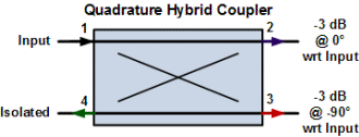
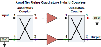
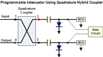
Typical Uses for a Directional Coupler The most common use for a directional coupler is to tap off a sample of the input power for use in signal monitoring circuits. That sample can be measured to determine the power level, frequency, and/or signal shape (modulation) and either presented for human viewing or can be integrated as part of a feedback loop that adjusts the output to stay within system specifications. When monitoring the voltage standing wave ratio (VSWR) of the load at the transmitted port, both the coupled port and the isolated port outputs are used to sample the incident and reflected power, respectively. This configuration is referred to as a bidirectional coupler. A special configuration of the directional coupler is referred to as a hybrid coupler, or a 3 dB coupler or a hybrid coupler or a "quadrature coupler," or a 3 dB hybrid coupler amongst other names. Regardless of what you call it, this coupler has the characteristics of dividing the input power into two paths that have equal powers when terminated properly. 3 dB Quadrature Hybrid Coupler The quadrature hybrid coupler has a unique property that makes it very useful for amplifier design, and that is when two equal, but not necessarily 50 Ω (or 75 Ω ,or whatever the system impedance) loads are connected to Port 2 and Port 3, Port 1 will "see" the system impedance (50 Ω, eg.) as long as that same 50 Ω is connected to Port 4. So, what that means is if you are designing a power amplifier with transistors that operate at, for example, 4.0 - j3.5 Ω input impedance and 1.5 - j2.5 Ω output impedance, a pair of them can be inserted between a set of quadrature couplers (Ports 2 and 3), with 50 Ω impedances at Port 1 and Port 4. Doing so eliminates the need to transform the transistor impedances, and the accompanying matching losses, to 50 Ω. The image below illustrates the hookup. Theoretically, an infinite number of these connections can be used. An added benefit of the balanced amplifier configuration is that both the IP3 and the P1dB is 3 dB greater than that of the individual devices. See this app note by Thomas Shafer. Quadrature Hybrid Coupler Ports Quadrature Hybrid Coupler Hookup for an Amplifier The same characteristic permits the hybrid coupler to be used as an attenuator. In this configuration, the signal input is on Port 1, and the output is taken on Port 4, the isolated port. Identical PIN diodes (and bias circuits) are connected to Port 2 and 3. When the diodes are turned off (usually requires a reverse bias to offset the negative portion of the RF voltage swing), Ports 2 & 3 'see' 50 Ω, and no power is reflected into the isolated port (Port 4). When the diodes are shorted (fully biased on), all of the signal is reflected back into the coupler and exits out of the isolated port (Port 4). Attenuation is therefore maximum when the PIN diodes are reverse biased and minimum when they are forward biased. The attenuator can also be realized using a pair of couplers a la the amplifier circuit above, where the PIN diode circuits are in the place of the transistors. Quadrature Hybrid Hookup for an Attenuator Thanks to Christian D. for providing additional content to this article. |
|||||||||||||||||||||||||||
