Introduction to Test Equipment |
||||||||||||||||||||||||||||||||||||||||||||||||||
|
NEETS Module 15 − Principles of Synchros, Servos, and Gyros Pages i, 1−1, 1−11, 1−21, 1−31, 1−41, 1−51, 1−61, 1−71, 2−1, 2−11, 2−21, 2−31, 3−1, 3−11, 3−21, 4−1, Index
Chapter 4
RELATED DEVICES
Learning Objectives
Upon completion of this chapter, you should be able to:
1. Compare standard synchro system connections with IC synchro connections.
2. Describe the operation of a step transmitter and receiver, and list the advantages and disadvantages of a step-transmission system.
3. Compare the construction and operation of a resolver to those of a transformer, describe the solution of resolution and composition problems by a resolver.
Some other devices that logically should be included in this module are the IC synchros, step motors, and resolvers. These are all electromagnetic devices used in various shipboard and aircraft applications. They can be considered as second cousins of the synchro.
IC SYNCHROS
The engine order telegraph, steering telegraph, rudder-angle indicator, and similar position- indicating systems used on naval ships are usually simple synchro systems. Some ships, however, use IC synchros to transfer such information. These units operate on the same general principle as the synchros we discussed in chapter 1.
The interior communication synchro (IC synchro) is gradually being phased out and replaced by standard synchros when replacement is required. However, you will still find some IC synchros in use today. For that reason, you will find some background information on their purpose and theory to be beneficial. We will present these synchros in very basic form in the following paragraphs.
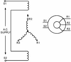
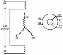
Because of their construction, IC synchros are sometimes called reversed synchros. The primary winding, consisting of two series-connected coils, is mounted physically on the stator. The secondary, consisting of three Y-connected coils, is mounted physically on the rotor. This is shown schematically in figure 4-1.
4-1
Figure 4-1. - IC synchro schematic diagrams.
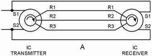
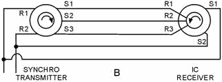
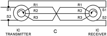
IC synchros operate on the same principles of interacting magnetic fields as other synchros, but differ in direction of shaft rotation and amount of torque obtainable. When an IC transmitter and IC receiver are connected in parallel as shown in view a of figure 4-2, the shaft of the IC receiver follows the rotation of the IC transmitter shaft. In view B, the IC transmitter is replaced by a synchro transmitter; the IC receiver shaft now turns in a direction opposite to that of the synchro transmitter. Voltages that cause counterclockwise rotation of a standard synchro shaft cause clockwise rotation of an IC synchro shaft. When it is desirable to have the IC synchro receiver turn in an opposite direction from that of the transmitter, the connections are as shown in view C. For a standard synchro receiver to follow the rotation of an IC transmitter, their connections must be made as shown in view D.
Figure 4-2A. - IC versus standard synchro connections.
4-2
Figure 4-2B. - IC versus standard synchro connections.
Figure 4-2C. - IC versus standard synchro connections.
Figure 4-2D. - IC versus standard synchro connections.
The torque obtainable from either an IC synchro or a standard synchro is determined by the magnetizing power, which is limited by the allowable temperature rise. When the stator is energized, as in IC synchros, the magnetizing power can be increased with a resulting larger torque. The reason for this is that the losses are dissipated in the form of heat around the outer shell of the IC transmitter or receiver. In standard synchros, this heat loss is dissipated through the rotor, the air gap, and then the outer shell to the surrounding air.
The electrical zero position for an IC synchro is the position where rotor coil R2 is aligned with the stator as shown in figure 4-1. To zero an IC synchro, apply the same general theory as we described for other synchros.
4-3 For further information on IC synchro replacement, alignment, and theory, refer to Military Handbook, Synchros, Description and Operation, (MIL-HDBK-225A).
Q-1. What two characteristics of IC synchros cause them to differ from standard synchros?
STEP-Transmission Systems
All of the synchro units we have discussed operate on alternating current. In applications where alternating current is not available, there is a need for a system that can use direct current. The STEP- Transmission System (sometimes referred to as the step-by-step system) is such a system.
A geared step-transmission system is often used to drive compass repeaters on naval vessels and merchant ships having dc power.
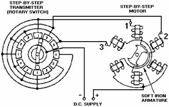
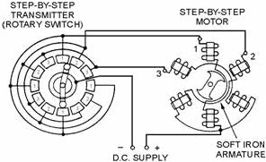
Although many variations are used, the simplified step-by-step transmission system shown in figure 4-3 is typical. In this system, a step transmitter and a step motor are used together to transmit angular data (information) between remote locations. When rotated, the shaft of the step transmitter periodically switches a dc excitation voltage from one pair of coils to another in the step motor. The step motor, which is the receiver in the system, responds to this varying excitation by rotating an amount that is proportional to the transmitter's shaft position.
Figure 4-3. - Step-by-step transmission system.
The stator of this step motor has six field coils spaced 60 degrees apart. The coils are connected in three groups of two coils each, with opposite coils connected in series. One end of each pair of coils is connected to one of the brushes in the step transmitter. The other ends of the coils are connected to the other side of the dc supply voltage through a common lead. As the rotor of the step transmitter is turned, the corresponding coils in the step motor are energized in sequence, producing a rotating step-by-step stator field. Thus, the motor rotates in abrupt increments or steps rather than smoothly.
4-4 Note: The theory of the step-by-step motor is similar to that involved in positioning the bar magnet (chapter 1, fig. 1-10).
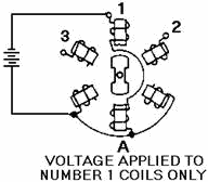
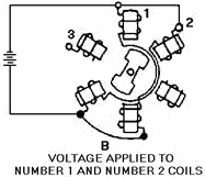
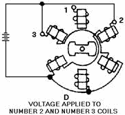
For ease of explanation, we will replace the step transmitter with a battery as we discuss the operation of the step motor. If, as shown in view a of figure 4-4, we apply the dc battery voltage across the number 1 coils only, the armature will turn to the position shown. When we apply the voltage also to the number 2 coils, the armature turns to a position midway between the number 1 and number 2 coils, view B. If we now disconnect the number 1 coils, the armature turns until it lines up with the number 2 coils, view C. View D shows the number 2 and 3 coils connected and the armature rotated one step further. As long as this process is continued, the armature can be rotated through 360 degrees.
Figure 4-4A. - Step-by-step motor in various positions. Voltage APPLIED to NUMBER 1 Coils ONLY.
Figure 4-4B. - Step-by-step motor in various positions. Voltage APPLIED to NUMBER 1 and NUMBER 2 Coils.
4-5
Figure 4-4C. - Step-by-step motor in various positions. Voltage APPLIED to NUMBER 2 Coils ONLY.
Figure 4-4D. - Step-by-step motor in various positions. Voltage APPLIED to NUMBER 2 and NUMBER 3 Coils.
In actual operation, the step-by-step motor is driven by a step transmitter (rotary switch) as shown in figure 4-3. As the switch is rotated, it applies voltage first to coil 1, and then in sequence to 1 and 2 together, coil 2 only, coils 2 and 3 together, coil 3 only, and so on, until the complete revolution is made. As a result, the armature turns in 30-degree steps that follow the rotation of the rotary switch. The rotating arm of the switch can be turned mechanically to angles between zero and 360º in 30-degree steps. The actual angle through which the arm is rotated depends on the specific data to be transmitted by the system. Real systems may transmit data in greater or lesser steps than 30 degrees, depending on system design.
An important point in this type of system is that because the armature is soft iron, either end of the armature may turn and line up with the energized coils. For this reason, a hand reset control is provided on the step-by-step motor. This permits an operator to align the receiver with the transmitter each time the power supply is energized.
4-6 A step-transmission system is not self-synchronizing, and its limited number of steps does not permit data to be transmitted smoothly or where relatively small changes in data are required. This type of transmission system is cheap, rugged, and relatively powerful.
Q-2. Compare the power sources of synchros and step-transmission systems. Q-3. a step transmitter is a modification of what electrical device?
RESOLVERS
The last device we will discuss is the resolver. Physically, resolvers are similar to synchros, and are used to perform mathematical computations electrically. They are rotary electromechanical devices that provide outputs that are trigonometric functions of their inputs. As you may know, the branch of mathematics that deals with the quantities and angles of a right triangle is known as trigonometry. Many "trig" problems that can be solved with paper and pencil can be solved by applying the proper electrical or mechanical quantities to a resolver. The resolver has the advantage of giving instantaneous solutions if the input quantities are changing continuously.
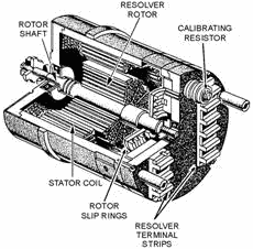
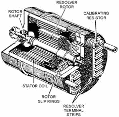
Resolvers are classified according to size (diameter) in the same manner as standard synchros and may be mounted with most standard synchro mounting hardware. a cutaway view of a resolver is shown in figure 4-5.
Figure 4-5. - Cutaway view of a resolver.
Notice that the stator of the resolver is a cylindrical structure of slotted laminations on which two coils are wound. The rotor is composed of a shaft, laminations, two windings, and four slip rings. Compensator components, which improve the angular accuracy of resolvers, may consist of resistors or additional windings in the stator and rotor winding circuits. Compensator windings, which increase the accuracy of the resolver, are located inside the stator. Compensating (calibrating) resistors, which
4-7 compensate for voltage inaccuracies and phase shifts, may be mounted either inside or outside the resolver housing.
A cylindrical frame with a standardized mounting flange houses the assembled resolver. External and internal connections can be made to an insulated terminal board on the rear of the housing. Miniature resolvers often have lead wires brought out through the rear of the resolver, eliminating the need for a terminal block. a reference line is scribed on the face of the housing for alignment with a similar line on the end of the rotor shaft. These are used in determining coarse electrical zero.
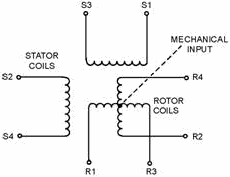
Basically, a resolver is a transformer in which the secondary windings can be rotated with respect to the primary windings. Consequently, the amount of magnetic coupling between the primary and the secondary is variable. In the most common form, a resolver consists of a stator and a rotor, each having two separate windings placed precisely at right angles to each other as shown in figure 4-6.
Figure 4-6. - Resolver schematic.
Since the two stator windings are physically and electrically at right angles to each other, there is no magnetic coupling between them. The stator windings are mounted on the resolver housing and are stationary with respect to it.
Similarly, the rotor windings of the resolver are wound at right angles to each other. Hence, there is no magnetic coupling between the two windings. The rotor windings are mounted on the rotor shaft and turn with it. The rotor is capable of unlimited rotation. Thus, the rotor windings can be set at any angle with respect to the stator windings.
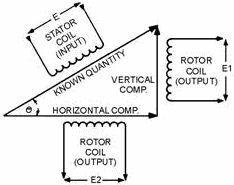
Because of the 90º physical and electrical relationships, the resolver has the ability to separate a quantity into its two right-angle components. This is called RESOLUTION.
Figure 4-7 illustrates the use of a resolver in solving a resolution problem. Assume that a voltage, E, and an angle, R, represent the magnitude and direction of a known quantity. To determine the two right- angle components of the quantity, feed the magnitude of the quantity to one stator coil and physically turn the rotor through angle R. The input voltage (E) induces voltage E1 and E2 in the two rotor coils. The values of these rotor voltages represent the vertical and horizontal components of the known quantity and depend on both the value of E and the angle (R) through which the rotor was turned.
4-8
Figure 4-7. - One example of resolution.
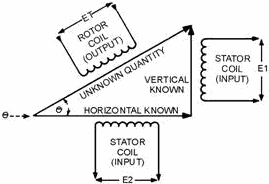
Similarly, the resolver has the ability to add two vectors that are at right angles to each other and produce the resultant vector (hypotenuse) at the resultant angle. This is called COMPOSITION.
Figure 4-8 illustrates one use of a resolver in solving a composition problem. Assume that we have two known quantities, vertical and horizontal components, that are represented by E1 and E2, respectively. Each of these is fed to a stator coil. These two voltages induce a voltage, ET, in one of the rotor coils. ET represents a voltage that is proportional to the hypotenuse. The voltage induced in the other rotor coils is fed to a closed-loop servo, which positions the rotor shaft to the angle (direction) of the hypotenuse.
Figure 4-8. - One example of composition.
Other mathematical solutions are possible to designers who apply resolvers in equipment. Typical naval problems solved by resolvers involve distances, speeds, angular quantities, etc.
In most cases, as in figures 4-7 and 4-8, only resolver coils actively used in solving a particular problem are shown in schematics.
4-9 Resolvers can also perform a third function Combination. This is the process of resolution and composition taking place simultaneously.
The resolver is a precision component, whose electrical characteristics are critical, and any deviation may result in excessive errors in the system. Before working on or replacing resolvers, you should check the associated equipment technical manual.
Q-4. What type of mathematical problem is solved by resolvers?
Summary
The following are brief summaries of the IC SYNCHROS, STEP-Transmission Systems, and RESOLVERS we covered in this chapter.
IC SYNCHROS, sometimes referred to as reversed synchros, are used in systems where transfer of information is desired. They operate on the same principles as synchros but differ in the direction of shaft rotation and amount of torque obtained.
A STEP-Transmission System (STEP-BY-STEP System) is similar to a synchro system, except that it is energized by direct current. This system uses a rotary switch to transfer angular data (information) between remote locations. The system is cheap, rugged, relatively powerful, but is not used where small changes in data are required.
4-10
RESOLVERS are physically similar to synchros and are used to perform mathematical computations. They are used extensively in analog computers, radar sets, direction and target designation equipment.
4-11
Answers to Questions Q1. Through Q4.
A-1. Direction of rotation and amount of torque.
A-2. Synchros use ac; step transmission uses dc.
A-3. Rotary switch.
A-4. Right-triangle, or trigonometric, problems.
4-12
|
||||||||||||||||||||||||||||||||||||||||||||||||||
