Module 8 - Introduction to Amplifiers
|
||||||||||||||||||||||||||||||||||||||||||||||||||
|
Module 8 − Introduction to Amplifiers Pages i, 1−1, 1−11, 1−21, 1−31, 2−1, 2−11, 2−21, 2−31, 3−1, 3−11, 3−21, 3−31, 3−41, 3−51, 3−61, AI−1, Index
Combination Peaking is accomplished by using both series and shunt peaking.
Low-Frequency Compensation is accomplished in a video amplifier by the use of a parallel RC circuit in series with the load resistor.
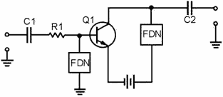
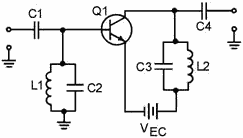
2-31 A Radio-Frequency (RF) Amplifier uses Frequency-Determining NetworkS to provide the required response at a given frequency.
The Frequency-Determining Network in an RF amplifier provides maximum impedance at the desired frequency. It is a parallel LC circuit which is called a Tuned Circuit
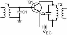
Transformer Coupling is the most common form of coupling in RF amplifiers. This coupling is accomplished by the use of RF transformers as part of the frequency-determining network for the amplifier.
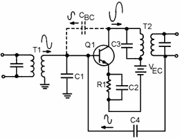
2-32 Adequate Bandpass is accomplished by optimum coupling in the RF transformer or by the use of a SWAMPING Resistor. Neutralization in an RF amplifier provides feedback (usually positive) to overcome the effects caused by the base-to-collector interelectrode capacitance.
Answers to Questions Q1. Through Q42. A-1. The difference between the upper and lower frequency limits of an amplifier. A-2. The half-power points of a frequency-response curve. The upper and lower limits of the band f frequencies for which the amplifier is most effective. A-3. (A) f2 = 80 kHz, f1 = 30 kHz, BW = 50 kHz (B) f2 = 4 kHz, f1 = 2 kHz, BW = 2 kHz A-4. The capacitance and inductance of the circuit and the interelectrode capacitance of the transistor. A-5. Negative (degenerative) feedback. A-6. It decreases. A-7. It increases. A-8. The capacitance of the circuit. A-9. Peaking coils. A-10. The relationship of the components to the output-signal path. A-11. Combination peaking. A-12. The coupling capacitor (C3). 2-33 A-13. a shunt peaking coil for Q2. A-14. a decoupling capacitor for the effects of R2. A-15. a part of the low-frequency compensation network for Q1. A-16. a series peaking coil for Q1. A-17. a swamping resistor for L2. A-18. L1, L2, and R5. A-19. R9 and C5. A-20. The gain increases. A-21. The gain decreases. A-22. To provide maximum impedance at the desired frequency. A-23. Yes. A-24. By changing the value. A-25. Transformer coupling. A-26. It uses fewer components than capacitive coupling and can provide an increase in gain. A-27. a step-down transformer. A-28. a too-narrow bandpass. A-29. By using an optimally-coupled transformer. A-30. Low gain at the center frequency. A-31. a swamping resistor in parallel with the tuned circuit. A-32. RF transformers are used and the transistor is neutralized. A-33. Degenerative or negative. A-34. By neutralization such as the use of a capacitor to provide regenerative (positive) feedback. A-35. C2 and the secondary of T1. A-36. R1 provides the proper bias to the base of Q1 from VBB. A-37. R2 provides the proper bias to the emitter of Q1. A-38. The output would decrease. (C4 decouples R2 preventing degenerative feedback from R2.) A-39. C5 and the primary of T2. A-40. Four. 2-34 A-41. The dotted lines indicate that these capacitors are "ganged" and are tuned together with a single control. A-42. C3 provides neutralization for Q1. 2-35 |
||||||||||||||||||||||||||||||||||||||||||||||||||
