Module 1 - Introduction to Matter, Energy, and Direct Current |
||||||||||||||||||||||||||||||||||||||||||||||||||
|
Module 1 − Introduction to Matter, Energy, and Direct Current
Pages i, 1−1, 1−11, 1−21, 1−31, 1−41, 1−51, 1−61, 2−1, 2−11, 2−21, 3−1, 3−11, 3−21, 3−31, 3−41, 3−51, 3−61, 3−71, 3−81, 3−91, 3−101, 3−111, 3−121, Appendix I, II, III, IV, V, Index
Figure 3-14. - Solving for total resistance in a series circuit.
In some circuit applications, the total resistance is known and the value one the circuit resistors has to be determined. The equation RT = R1 + R2 + R 3 can be transposed to solve for the value the unknown resistance. Example: In figure 3-15 the total resistance a circuit containing three resistors is 40 ohms. Two the circuit resistors are 10 ohms each. Calculate the value the third resistor (R3).
3-21
Figure 3-15. - Calculating the value one resistance in a series circuit.
Current in a Series Circuit Since there is only one path for current in a series circuit, the same current must flow through each component the circuit. To determine the current in a series circuit, only the current through one the components need be known. The fact that the same current flows through each component a series circuit can be verified by inserting meters into the circuit at various points, as shown in figure 3-16. If this were done, each meter would be found to indicate the same value current.
3-22
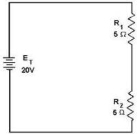
Figure 3-16. - Current in a series circuit. Voltage in a Series Circuit The voltage dropped across the resistor in a circuit consisting a single resistor and a voltage source is the total voltage across the circuit and is equal to the applied voltage. The total voltage across a series circuit that consists more than one resistor is also equal to the applied voltage, but consists the sum the individual resistor voltage drops. In any series circuit, the SUM the resistor voltage drops must equal the source voltage. This statement can be proven by an examination the circuit shown in figure 3-17. In this circuit a source potential (ET) 20 volts is dropped across a series circuit consisting two 5-ohm resistors. The total resistance the circuit (RT) is equal to the sum the two individual resistances, or 10 ohms. Using Ohm's law the circuit current may be calculated as follows:
3-23
Figure 3-17. - Calculating individual voltage drops in a series circuit. Since the value the resistors is known to be 5 ohms each, and the current through the resistors is known to be 2 amperes, the voltage drops across the resistors can be calculated. The voltage (E1) across R1 is therefore:
By inspecting the circuit, you can see that R2 is the same ohmic value as R1 and carries the same current. The voltage drop across R2 is therefore also equal to 10 volts. Adding these two 10-volts drops together gives a total drop 20 volts, exactly equal to the applied voltage. For a series circuit then:
ET = E1 = E 2 + E3 = . . . En Example: a series circuit consists three resistors having values 20 ohms, 30 ohms, and 50 ohms, respectively. Find the applied voltage if the current through the 30 ohm resistor is 2 amps. (The abbreviation amp is commonly used for ampere.) To solve the problem, a circuit diagram is first drawn and labeled (fig 3-18).
3-24
Figure 3-18. - Solving for applied voltage in a series circuit.
Substituting:
3-25 Note: When you use Ohm's law, the quantities for the equation MUST be taken from the SAME part the circuit. In the above example the voltage across R2 was computed using the current through R2 and the resistance R2. The value the voltage dropped by a resistor is determined by the applied voltage and is in proportion to the circuit resistances. The voltage drops that occur in a series circuit are in direct proportion to the resistances. This is the result having the same current flow through each resistor - the larger the ohmic value the resistor, the larger the voltage drop across it. Q17. a series circuit consisting three resistors has a current 3 amps. If R1 = 20 ohms, R2= 60 ohms, and R3 = 80 ohms, what is the (a) total resistance and (b) source voltage the circuit? Q18. What is the voltage dropped by each resistor the circuit described in question 17? Q19. If the current was increased to 4 amps, what would be the voltage drop across each resistor in the circuit described in question 17? Q20. What would have to be done to the circuit described in question 17 to increase the current to 4 amps? Power in a Series Circuit Each the resistors in a series circuit consumes power which is dissipated in the form heat. Since this power must come from the source, the total power must be equal to the power consumed by the circuit resistances. In a series circuit the total power is equal to the SUM the power dissipated by the individual resistors. Total power (PT) is equal to: PT = P1 + P2 + P3 . . .Pn Example: a series circuit consists three resistors having values 5 ohms, 10 ohms, and 15 ohms. Find the total power when 120 volts is applied to the circuit. (See fig. 3-19.)
Figure 3-19. - Solving for total power in a series circuit.
3-26 Given:
Solution: The total resistance is found first.
By using the total resistance and the applied voltage, the circuit current is calculated.
By means the power formulas, the power can be calculated for each resistor:
To check the answer, the total power delivered by the source can be calculated:
3-27
The total power is equal to the sum the power used by the individual resistors. Summary Characteristics The important factors governing the operation a series circuit are listed below. These factors have been set up as a group rules so that they may be easily studied. These rules must be completely understood before the study more advanced circuit theory is undertaken. Rules for Series DC Circuits 1. The same current flows through each part a series circuit. 2. The total resistance a series circuit is equal to the sum the individual resistances. 3. The total voltage across a series circuit is equal to the sum the individual voltage drops. 4. The voltage drop across a resistor in a series circuit is proportional to the ohmic value the resistor. 5. The total power in a series circuit is equal to the sum the individual powers used by each circuit component. Series Circuit ANALYSIs To establish a procedure for solving series circuits, the following sample problems will be solved. Example: Three resistors 5 ohms, 10 ohms, and 15 ohms are connected in series with a power source 90 volts as shown in figure 3-20. Find the total resistance, circuit current, voltage drop each resistor, power each resistor, and total power the circuit.
Figure 3-20. - Solving for various values in a series circuit.
3-28 In solving the circuit the total resistance will be found first. Next, the circuit current will be calculated. Once the current is known, the voltage drops and power dissipations can be calculated.
3-29
Example: Four resistors, R1 = 10 ohms, R2 = 10 ohms, R3 = 50 ohms, and R4 = 30 ohms, are connected in series with a power source as shown in figure 3-21. The current through the circuit is 1/2 ampere. a. What is the battery voltage? b. What is the voltage across each resistor? c. What is the power expended in each resistor? d. What is the total power?
Figure 3-21. - Computing series circuit values.
3-30
|
||||||||||||||||||||||||||||||||||||||||||||||||||