Using Simulation Tools to Troubleshoot an LC Filter Design |
|
Note: Ed Troy, owner of Aerospace Consulting, LLC, was kind enough to offer a few of his articles for posting on RF Cafe. With more than 30 years in the electronics communications design field, Ed has a lot of valuable knowledge to impart to us mortals ;-) This first paper discusses a method for accommodating real-world stray capacitances in the simulation model for helping to assure first-pass success on LC filter designs. He's a highly rated airplane pilot as well, which counts for something in my book. Stay tuned for others...
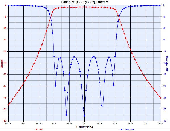
Using Simulation Tools to Troubleshoot an LC Filter Design By Ed Troy, Aerospace Consulting, LLC Almost everyone uses simulation tools for designing RF, microwave, and high speed digital circuits today. It is essential. But, very few engineers use those same tools for troubleshooting of circuits that are not working correctly. It amazes me that many engineers and technicians still spend days tuning, tweaking, and adjusting RF circuits that do not work properly on the bench. They could probably find, and fix, the problems in much less time by firing up their simulation software. It is much faster to change values, both known and speculated, in a simulation engine than it is to make the same changes on the test bench. I was first introduced to the power of using simulation to troubleshoot circuits in the early 1980's. I was working on a receiver that required a 70 MHz IF band pass filter. While many people may consider 70 MHz to be VHF, or very high frequency, or even UHF, or ultra high frequency, I thought of it as a pretty low frequency, since I was used to working at frequencies up to 18 GHz. But, when my technician tested a 70 MHz band pass filter that I had designed, it did not work at all as expected. In fact, the performance was so bad that I thought that perhaps someone had mixed up the capacitors or inductors and thus installed the wrong values. So, I had the technician rebuild the circuit using components whose values had been actually measured. The results were the same. The filter looked terrible. This happened over 30 years ago, so I do not have the original design files or test results, but I can reproduce them very easily in a circuit simulator. Lets say we need a 70 MHz band pass filter with a bandwidth of 5 MHz. A few minutes with the Keysight (formerly Agilent) Genesys filter design tool produces the following circuit (figure 1) and response(figure 2).
Figure 1 - Ideal 70 MHz Band Pass Filter Design
Figure 2 - Filter Response of Filter in Figure 1
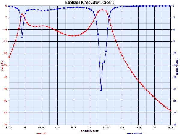
This looks pretty good! But, when my technician built it up, as I said, we got a response similar to what is shown in figure 3.
Figure 3 - Measured Response of Circuit in Figure 1
OOPS! Something is obviously wrong. But, we measured the values and the inductors and capacitors were the correct values. What could be wrong? After looking at the situation for a while, I realized that there was a pad on the circuit board where L1 and C1, L3 and C3, and L5 and C5 came together. Those pads were only about 0.1" x 0.1" in size, however. How could those tiny pads matter? A quick calculation showed that those pads had a capacitance to ground of about 0.22 pF. How did I come to that conclusion? By using the equation for a parallel plate capacitor. In our case, k, the relative dielectric constant of our circuit board material was 3.3. E0 is a physical constant. The necessary calculations are shown below, where the equation for the capacitance of a parallel plate capacitor is shown by the equation for C0:
Since the pad is 100 mils square, or 0.1" x 0.1", and there are 0.0254 m/in
The board thickness was 33 mils, or .033 inches, or .033*.0254 meters
Again, so what? Well, let's re-simulate the circuit putting 0.2 pF capacitors at those points, as shown in figure 4.
Figure 4 - Filter Circuit with Calculated Spurious Capacitances Added to Schematic
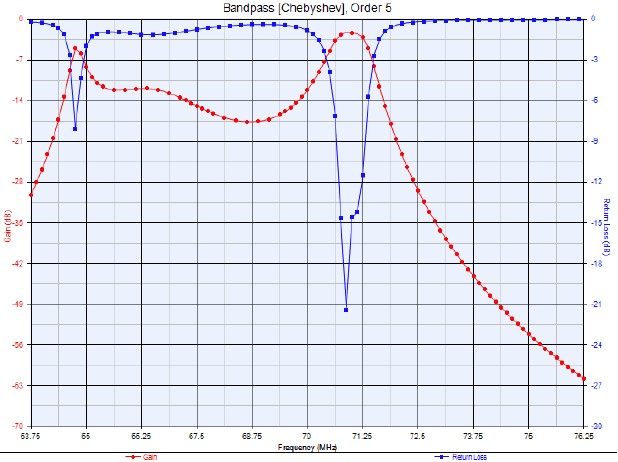
The result of that re-simulation is shown in figure 5.
Figure 5 - Simulation Result for Circuit in Figure 4
This is the same as the measured result. (Of course it is the same in this case since I used the simulator with the 0.2 pF capacitors added to produce the "measured" result. But, trust me, the result we saw when we measured the filter circuit in the early 1980's was very close to the "measured" result that I am using in this paper. I no longer have access to the actual circuit board or the decades old measured data.) So, the small, 0.22 pF stray capacitances of the pads where the series L and C components were soldered to the board apparently created the terrible filter response. So, now what? We have to have those pads. Without them, the circuit could not be built. Let's redesign the filter with those pad capacitances as fixed. We will adjust the values of everything else to work properly with the 0.22 pF stray capacitances of the board pads. This optimization results in the circuit shown in figure 6 and the results are in figure 7.
Figure 6 - New Circuit. The 0.22 pF Capacitors Are Strays and Not Part of the Populated Parts
Figure 7 - Simulated, Optimized Circuit Response with 0.22 pF Stray Capacitances
While not identical to the original circuit simulation, this represents a usable filter which we built up and used. (Of course, any experienced engineer recognizes that the values in these simulations are ideal and not actual values of capacitance and inductance that can be purchased. But, by using standard value inductors and capacitors we were able to get adequate performance once we re-optimized the circuit given the 0.22 pF stray capacitances due to the physical pads on the boards that were necessary to connect the series L and C capacitors.) Of course, we could have spent days changing values on an actual circuit board to eventually arrive at the necessary performance, but it was much faster (and thus less expensive) to use RF simulation software tools to do the troubleshooting and to come up with a great design. To download an Adobe Acrobat copy of this paper, click here.
Copyright 2015, Aerospace Consulting LLC. All rights reserved.
About Aerospace Consulting, LLC Aerospace Consulting was started in 1982 as a part-time business. The founder, Ed Troy, had just changed jobs from working for a company that made telemetry transmitters and other military communications equipment to a company that produced electronic article surveillance equipment. While working at ICI Americas, Ed had an opportunity to do some design consulting with a company in New York that made hardware related to anti-submarine warfare. Additionally, Narco Avionics needed help in redesigning some DME hardware because the transistor used in their high power pulse transmitter was no longer available and a new amplifier had to be designed and developed. With permission from ICI America's management, Ed started consulting on a part-time basis for these companies that were clearly not competitors of ICI's EAS business. At the same time, Ed, a pilot with commercial, multi-engine, and instrument ratings, was brokering aircraft in his free time. So, given the work for 2 aerospace-related companies and the fact that he was brokering aircraft, Aerospace Consulting seemed a natural name for the company. Today, it might seem a bit of a misnomer since most of Aerospace Consulting's customers are not aerospace companies (although some are), but the name has not been changed. In the 25 years since going full-time, Aerospace Consulting has grown dramatically both in terms of capabilities as well as the types of businesses served. Aerospace Consulting also works with companies, both large and small, that have plenty of RF, microwave, and wireless facilities and employees, but they just need some extra help to get through an especially busy time.
Posted March 5, 2015 |