RF Connectors and Cables |
|
Sunshine Design Engineering Services
Joe Cahak, owner of Sunshine Design Engineering Services, has submitted another fine article for posting here titled, "RF Connectors and Cables." It is a very nice treatment on various flavors of coaxial cables and connectors that includes specifications on the most commonly used types, governing equations, and recommendations on proper care and cleaning. Joe has also provided a list of the manufacturers, industry standards, and technical references he has found most useful during his many decades of automated RF testing experience. "RF Connectors and Cables" serves as a great introduction for newcomers to the RF and microwave realm, as well as a quick reference for bookmarking regardless of your experience level.
RF Connectors and Cables By Joe Cahak June 9, 2014 This article will explore RF connectors and cables. We will also look into the means to take care and maintain their quality and lengthen their lifetime. Cables and connectors are crucial to modern test and measurement at DC to audio through millimeter wavelengths. The type of signal or energy being applied will determine what cables and connectors are appropriate for the job. DC power transfer is quite different from RF power transfer. For one thing the frequency of the RF signal plays a large role in the quality of signal transmission due to frequency dependency of transmission cables and connectors based on their construction. For DC power only the insulation type, conductor current, power handling, thermal characteristics and the tensile strength for physical challenges at the usage location are major considerations. The AC power (60 cycles per second, or Hertz) in the U.S. is low enough in frequency that many of the interconnections are similar to DC conductors with some considerations for AC. At DC and 60 Hz AC we typically see solid or stranded conductors. Coaxial (coax) cable for RF transmission can come in single conductor, dual wire (Triaxial) or with even an even larger number of conductors. Although typically sheathed in plastic, the many commercial and government broadcast stations and radar use rigid or flex tube (semi-rigid) coax.
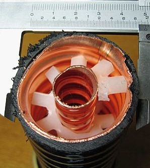
Figure 1 - Commercial Broadcast Coaxial Cable Tube
When the cable is underground the local soil mineralization (from magnetic minerals like hematite) or close proximity conductive metal structures can induce electrical/magnetic currents or eddies. These currents cause AC line losses unless shielded and even then still could experience some losses. As you increase the frequency to audio (20-20,000 Hz) and above, how the signal is carried must change to get good transmission of signal at the higher frequencies. At audio frequencies typically either twin wire (balanced) or coaxial (unbalanced) cable is used. Each of these has different qualities or characteristics. Twin wire is low loss, but prone to external influence from coupling of electric or magnetic fields. Coaxial has better shielding from external signals, but higher losses. As the frequency increases the "skin effect" becomes more prominent. As the frequency is increased the depth through which the RF current flows inside the conductor decreases and localizes to the skin (outside surface) of the conductor, whereas at DC and AC (60 Hz) the current is through the conductor's entire cross-section. Skin depth or
ρ = resistivity = 1/σ = ohm/meter σ = electric conductivity = meters/ohm F = Frequency (Hz) μr = relative (to μ0 ) permeability constant μ0 = free space permeability constant = 4π × 10−7 H·m−1 ≈ 1.2566370614 × 10⁻⁶ H·m−1 or N·A−2 μ = μ0μr
Characteristic Impedance plays a much larger role at frequencies above 100 kHz in the quality of the signal transmission quality. The impedance we call characteristic is different than resistance loss. This impedance is a characteristic of the cable with high frequency signals. The characteristic impedance of coaxial cables in ohms is:
D = outer diameter (any unit of length, but must be same as 'd') d = inner diameter (any unit of length, but must be same as 'D') ε0 = free space permittivity in a vacuum = 8.8541878176 × 10⁻¹² F/m εr = relative permittivity or dielectric constant ε0 = ε0εr Another interpretation of Z the characteristic Impedance is
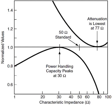
L = inductance per unit length and C = capacitance per unit length Typical coaxial impedances are 50, 75 and 93 ohms. 50 ohms is the most common. A typical question is why 50 ohms? Wikipedia has the most through answer I have found. The best coaxial cable impedances in high-power, high-voltage, and low-attenuation applications were experimentally determined at Bell Laboratories in 1929 to be 30 Ω, 60 Ω, and 77 Ω, respectively. For a coaxial cable with air dielectric and a shield of a given inner diameter, the attenuation is minimized by choosing the diameter of the inner conductor to give a characteristic impedance of 76.7 Ω. When more common dielectrics are considered, the best-loss impedance drops down to a value between 52–64 Ω. Maximum power handling is achieved at 30 Ω. The arithmetic mean between 30 Ω and 77 Ω is 53.5 Ω; the geometric mean is 48 Ω. The selection of 50 Ω as a compromise between power-handling capability and attenuation is in general cited as the reason for the number.- courtesy of Wikipedia.
Figure 2 - Coaxial Cable Impedances
The coaxial cutoff frequency is the highest frequency for which only transverse electromagnetic (TEM) waves will be supported, above which other modes (TEn,m and TMn,m) will propagate and cause phase interference. In MHz equation is:
D and d and c must have the same length units. The coaxial shunt capacitance in Farads/meter (C/m):
The coaxial series inductance in Henrys/meter (L/m):
The coaxial velocity of propagation in meters/sec:
c = 3.0 x 10⁸ m/s For PTFE Length (meters/cycle) =
Phase Shift (degrees) =
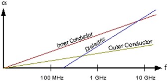
εr = relative dielectric constant f = frequency l = Length (m) δ = dielectric loss tangent ρrd = resistivity of inner conductor relative to copper ρrD = resistivity of outer conductor relative to copper
Figure 3 - Coaxial Cable Loss (courtesy RFCafe.com)
Peak Voltage is set by the breakdown voltage of the insulator: S is the Insulator breakdown in Volts/mil d = inner dia. (m) D = outer dia. (m)
Peak Power is the maximum power the coaxial cable can handle. At this power the dielectric can breakdown and fail.
Ed = Electric Field δ0 = impedance of free space 377 ohms
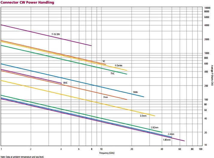
Figure 4 - RF Connector Power Handling Capability (courtesy MegaPhase)
Coax cables can be subject to shielding issues with leakage, braded shields are worse than full shield and loose interconnects with the cable connectors also cause leakage. They can also be affected by common mode currents, current loops, noise, transformer effects and radiation. RF Connectors Let's take a look at some of what RF coaxial connectors are available today. We have connectors from BNC at the low frequency end to the X connector for millimeter wavelengths. Each has specific properties based on the frequency range served and the quality of the connection, the measurement being made with the cable and the amount of expense willing to be paid for quality connectors. The connector types vary in dimensions and dimensional accuracy and fit. Each connector serves a quality and economic fit in the market. BNC connectors, for instance, are a widely used connector at DC thru 1 GHz with reasonable quality. The higher the frequency above 1 GHz, the higher the connector dimensional tolerances and connector materials play a significant role in the cost and performance. Surprisingly many very high bandwidth Oscilloscopes, bandwidths of 20 GHz and higher, are still using BNC connectors, high performance variants to be sure.
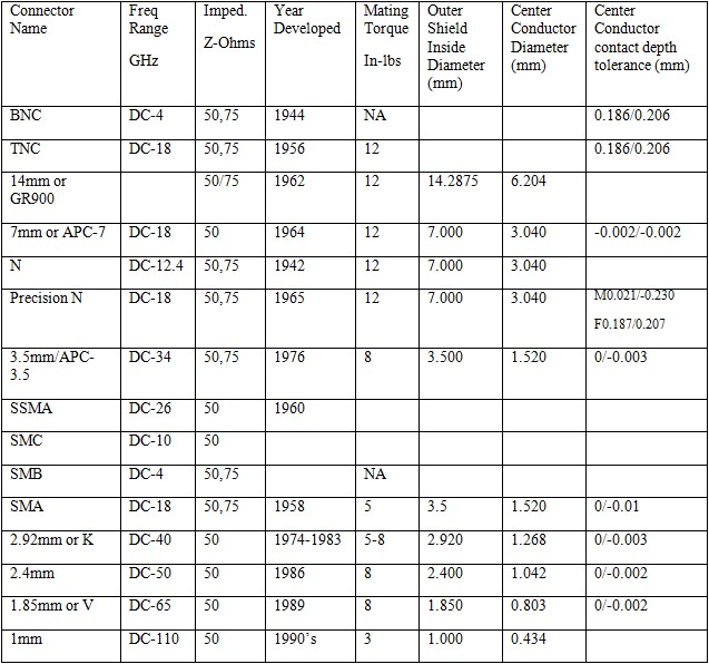
RF Coaxial Connector Types
Connector Specifications The following documents are some of the connector specifications for dimensions and tolerance as well as all the design drawings and electrical specifications. IEEE Standard 287-2007 IEC Publication 457 MIL-STD-348A incorporates MIL-STD-39012C IEC Publication 169 CECC 22000 British Standard 9210 DIN Standards The Megaphase Connector Technical Reference is an excellence resource for the connector reference standard documents. Connector Dimensioning and Gauging There are caliper gauges available for measuring precision connectors for such things as pin diameter and depth, socket interface depth and tension of spring collets if it has them (APC-7). Any suspect connector should be gauged to insure it will not damage other connectors if used. All major connector and cable assembly manufacturers gauge everything they ship. Ask to make sure your distributer or source has done this, as the cheap connector and cable assemblies may be out of dimensional tolerance. The best references I have found for coaxial connectors and the proper use and maintenance of can be found in these 3 industry standard references: https://www.maurymw.com/pdf/applib/5A-035.pdf https://cp.literature.agilent.com/litweb/pdf/08510-90064.pdf https://www.hparchive.com/Application_Notes/HP-AN-326.pdf Microwave Measurements by Collier and Skinner is another excellent reference. Connector Repeatability The following table gives some of the typical expected repeatability for the connectors listed and where said connectors and cables are kept in good shape. The repeatability of the electrical performance quality and the mechanical quality of the cables and connectors determine the lifetime of them. SMA connectors are rated for about 100-1000 connections depending on whether plated brass or stainless steel connectors. APC3.5 mm may have a lifetime of 1000-10000 connections. So it may be worth it to spend a bit more to have quality connections with less trouble. If your repeatability is greater than this, check your system over for bad connections.
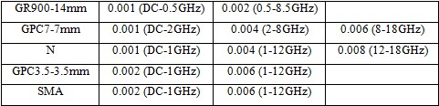
Table 1 - Connector Insertion Loss Repeatability in dB
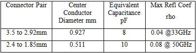
Connector Adaptability Some of the most used microwave connectors can adapt to different connectors. There are electrical and mechanical issues to those interfaces, but they can be done in a pinch. SMA, APC3.5 mm and 2.92 mm or K connectors can all be adapted to each other. 2.4 mm and 1.85 mm are also adaptable. The issues are the tolerance on the dimension and alignment of the pins. The lower quality SMA can damage the 3.5mm or 2.92mm connectors and should be gauged prior to using them. SMA center pin and socket has a gauge dimension tolerance of +/-0.01 and APC3.5 mm has +/-0.003. SMA connectors that are out of tolerance can damage the 3.5 mm precision connector or 2.92 mm that SMA can both adapt to. The electrical characteristics of the mismatch interface should be accounted for in vector phase measurements. Both sets of connection mating have a capacitive discontinuity at the junction. This is due to the surfaces not completely mating leaving air gaps with charge across them causing capacitance at the gap.
Table 2 - Capacitive Discontinuity for Unlike Coaxial Connector Mating
Use of adapters or connector savers with any connection will degrade the connection to some or a significant extent. But when connecting to suspect test gear, using a connector saver can save a more expensive connector repair on an instrument or other devices. So use wisely. The VSWR or match is the main electric performance issue as is the capacitive or inductive parasitic from the mismatched interface. The lower quality microwave connectors such as N, SMA have slotted center sockets to accept the male pins and they expand to hopefully the same diameter as the inside center conductor. This expansion can cause impedance changes if not matched to precisely the same diameter as the center coax conductor. Most of the modern precision connectors (7 mm, 3.5 mm, 2.92 mm, 2.4 mm, 1.85 mm & 1.0 mm) use a solid outer wall on the center socket and the expanding slotted spring flanges to make contact inside the center socket. So when the pin is inserted, the diameter of the pin-socket interface is constant and the best match at the interface is made. Connector Match Connectors properly cleaned and with proper connection torque, can provide very repeatable and stable connections for measurements or communication systems. The quality of the match or interface between connectors is the SWR or VSWR. SWR is a measure of the ratio of the power or voltage reflected to power or voltage incident on a connection.
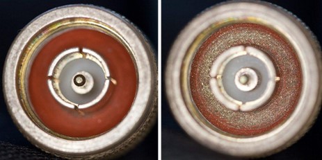
When you have systems with connections each connection has a match. The mismatch loss can be calculated with MismatchdB = -20 x log10 (1 ± ρ2) These connection matches do not add linearly, when there are multiple system connections. The total worst case mismatch can be calculated in dB with the formula Max MismatchdB = -20 x log10 (1 ± |ρ1 ρ2|) ρ1 = match at connection 1 ρ2 = match at connection 2 Impact of bad cables and connectors Using cables to test with can be an exercise in futility in a lab that takes poor care of the cables and connectors. Most connection issues and problems are due to the poor care of connectors, adapters and cables. Cables can be deformed during manufacturing, shipment, assembly or during use from extreme temperatures and/or flexure. Coax cable, if bent too sharp, can crimp the dielectric filling causing discontinuities in the impedance of the cable. Too much pull (tension) or side pull can damage the cable to connector interface (or boot) as well as the connector; pressure on the connector can deform it. Most cable manufacturers put a boot around the cable to connector interface to strengthen the connection. Some even put bends that are thermo-formed in the boot section. This will prevent connector interface deformations and separation which can certainly cause a discontinuity in the desired signal conducting quality. Another less well known undesirable for cables is for high precision vector network analysis applications. This is a measurement environment where good phase stable cables are a requirement to hold fair calibrations with temperature change and flexure. Solid dielectric cables will deform with flexure and bending as well as with temperature changes. Vector Network measurement applications, where phase is important, the test operator should be using phase stable cables. Gore-Tex came out with a foamy dielectric that helped by allowing compression or temperature changes to occur without changing the dielectric constant of the cable and preserving the impedance. Other manufactures have other types and topologies of dielectric to accomplish the same thing. MegaPhase uses a spiral wrapped dielectric material that is lower cost and just as effective. I have found their test cables to hold to their phase offset specs for flexure and temperature change. I was getting good results down to 1.5" radius bends in the cable and over the typical -30 to 70 °C test temperature range. For all these consideration, as well as reasonable cost, service and repair-ability of the connectors on the cables, I recommend MegaPhase cables for all high precision measurements with Vector Analyzers. Megaphase cables have a very good quality and price. They are repairable and have a unique connector ferrule that solders to the cable end for the connector attachment enabling their easy reparability. I also find the connectors hardened and last for many connections. They also have a very good booting system to make the cable to connector interface quite rugged and durable. They deliver fast and will work with customers to provide rapid cable delivery. I find the Megaphase Killer Bee and Orange cables are both of high quality for Vector Analyzer measurements. They help hold calibrations and keep mismatch ripple down. They are also very flexible and rugged. Other may be as good, but do check for these standards for performance and cost. Companies I currently use and recommend: https://www.firstsourceinc.com/default.aspx https://www.hubersuhner.com/en/ Connector/Cable Selection What do we look for when we make a connector selection? Desired qualities are frequency response, match quality, mechanical strength and resilience of the cable and connector, the connector dimensional accuracy (tolerance), the connector metal wear characteristics (plating and machining) and electrical performance. The type of cables and connectors are also heavily dependent on the usage or application. If you are making high quality precision measurements, then you should use high quality phase stable cables like the Killer Bee cables from Megaphase. If you have high volume production RF test environment I would choose the lower cost Orange cables from MegaPhase. If placing cables in a test interface box or test system, the requirement can change. Inside a test interface box, I will use tinned braided coax with SMA or APC3.5 mm connectors and the cables are easily formable and can be cut to size easily when using crimp-on connectors. First Source has been a great source for these. These tinned copper or copper jacketed cables would have to be shielded for mechanical forces (bumping, vibration, excess heat etc) to prevent damage or bad performance. In a test environment with simple tests for power, spectral analysis or other non-phase sensitive measurement these lower cost cables are fine. If frequencies are below 1 GHz and low accuracy measurements I would typically use BNC connectors for low cost and easy adaptability. So there are a lot of difference connector and cable selections based on the usage, environment they are in and the quality of the connection and signal transmission characteristics. Connector Care How do we keep our cables and connectors in good shape and making good measurements for as long as possible? By inspecting the cables and connectors and doing some preventative cleaning, also by taking care of how we use and store our cables and connectors. For the cables we look to the external characteristics. Is the cable crimped or bent out of shape? Is the cable to connector boot still good and solid and not frayed or loose? With Male connectors are the center pins straight and not bent or damaged? Female sockets check they are clean and in good mechanical shape. Is there spring in the spring center collets, if they have one? If you look at the inside of the connector you can see if there is any debris that causes gaps and mismatch as well as difficult turning of the connector nut. The example below clearly shows the difference in quality of the connector.
Figure 5 - Clean and Dirty N Male Connector (courtesy Kenneth Wyatt/EDN)
The wear debris is made up of metal particles from the connector plating and body material wearing. This debris can cause poor turning, added wear on the connector moving (rotating or sliding) parts and RF performance degradation. So first and foremost the most important means to keep the connector operating well and easy to work with is to keep them clean. For solid dielectric connectors like BNC, TNC, SMA, SSMB and a couple others alcohol and a lens tissue or cotton swab can be used to clean the surfaces. Check with a microscope or lens to insure fiber, dirt and film free. If using alcohol solvent to flush the connectors, use only in a well ventilated area. Caution for explosive vapor. To clean inside the connector joint, turn the connector upside down and wrap an absorbing cloth/tissue around the connector body to catch the excess liquid, pour a bit of alcohol into the connector and rotate to flush the joint. The connector will now turn more freely. Be sure to do this in a well ventilated area and to dispose of the tissue in the same well ventilated solvent disposal areas. Wipe the connector surfaces clean of residual films and if possible use a bit of air pressure to clean and get particles out. High quality high frequency connectors such as APC-3.5, APC-7, K or 2.92 mm, 2.4 mm, 1.8 mm or V and 1.0 mm require special cleaning and care. You cannot use liquids or fibrous materials as they may leave a film or fibers behind, which will impact the quality of the connection. Never use any oil. I would strongly recommend reading the Maury Microwave and Agilent app notes I have links to. They have very specific information and detailed mechanical tolerance details for each of the connectors. How to clean each type and check each for damage and in some cases how to repair or replace components such as the center collets on the APC-7mm for instance. In Agilent App Note 326, which was published in the 1980's, they used liquid Freon. This is of course no longer available and is illegal to use. In cases where the connector does not have a solid dielectric, like some APC3.5mm, all 2.92 mm, 2.4 mm, 1.85 mm and 1.0 mm connectors, which have air dielectric, the connector structures have air gaps and pockets that can collect debris that degrades performance. Most experts recommend compressed air to clean these out. Solvents have surface tension that tends to capture particles in the liquid and transport them into the crevices and gaps. For these high frequency and quality connectors these liquid solvents are not recommended. Next point is to use proper torque to make safe consistent connections. I saw one connector article where the author actually said to generally use "finger tight". While this may be OK for some connectors, for the 1.0 mm, finger tight can cause damage. So check the references for best results. In addition hand tightening can also lead to inconsistent connections and measurement results. Finally check cables for normal loss prior to critical use. Flex the cable while checking to make sure the boot and connector are tight and the loss stays consistent with some flexure. Pay attention to the care and usage of your cables and connectors and you can easily extend their quality and useful life. Links: https://www.edn.com/electronics-blogs/the-emc-blog/4424332/Clean-Those-Connectors https://ecee.colorado.edu/~kuester/Coax/connchart.htm https://www.microwaves101.com/encyclopedia/connectors.cfm https://www.microwaves101.com/encyclopedia/coax_power.cfm https://www.micro-coax.com/technical/precision-microwave-assembly-care-handling-instructions/ https://www.megaphase.com/documents/Technical_Reference.pdf Books: Microwave Measurements, Collier and Skinner, The Institute of Engineering and Technology, 978-086341-735-1 Handbook of Microwave Measurements with Advanced Techniques, Joel P. Dunsmore, Wiley, 978-111997-955-5 Microwave Engineering Passive Circuits, Peter A. Rizzi,Prentice Hall,0-13-586702-9 The RF and Microwave Handbook, Mike Golio, CRC Press,0-8493-8592-X App Notes: https://www.maurymw.com/pdf/applib/5A-035.pdf https://cp.literature.agilent.com/litweb/pdf/08510-90064.pdf https://www.hparchive.com/Application_Notes/HP-AN-326.pdf https://en.wikipedia.org/wiki/Coaxial_cable https://www.megaphase.com/documents/Technical_Reference.pdf Vendors: https://www.mountztorque.com/learning-center/article/proper-torque-control-rfcoax-sma-connectors https://www.radiall.com/products/rf-coaxial-connectors https://www.ie.itcr.ac.cr/marin/lic/el4515/HUBER+SUHNER_RF_Connector_Guide.pdf https://www.te.com/catalog/minf/en/119 https://www.l-com.com/coaxial-connectors https://www.pasternack.com/connectors-category.aspx?gclid=CMK6haLv3rwCFQZrfgodGQ8ADA https://www.firstsourceinc.com/default.aspx https://www.hubersuhner.com/en/
Sunshine Design Engineering Services is located in the sunny San Vicente Valley near San Diego, CA, gateway to the mountains and skies. Are you looking for new things to design, program or create and need assistance? I offer design services with specialties in electronic hardware, CAD and software engineering, and 25 years of experience with Test Engineering services in RF/microwave, transceiver and semiconductor parametric test, test application program development, automation programs, database programming, graphics and analysis, and mathematical algorithms. See also: - Noise and Noise Measurements - Measuring Semiconductor Device Input Parameters with Vector Analysis - Computing with Scattering Parameters - Measurements with Scattering Parameters - Ponderings on Power Measurements - Scattered Thoughts on Scattering Parameters Sunshine Design Engineering Services 23517 Carmena Rd Ramona, CA 92065 760-685-1126 Featuring: Test Automation Services, RF Calculator and S-Parameter Library (DLL & LLB)
Posted June 30, 2014 |