Bias-T, Band Splitter and Other RF Diplexers
|
|
White Papers
You are welcome to submit yours. The following article / app note titled, "Bias T, Band Splitter and Other RF Diplexers," was submitted to RF Cafe by Bree Engineering. It is a brief introduction to and explanation of the theory and application of the named frequency selective devices. A Bias-T is frequency dependent just as much so as a band splitter or diplexer; it differentiates between DC (0 Hz) and the RF frequency. Bree Engineering Corporation was founded in 1999 and is a manufacturer of custom electronic filters, multiplexers, filter banks and other related types of components in the frequency range of 0.1 MHz to 40 GHz. Designs include Chebychev, Bessel, Butterworth, Gaussian, transitional, elliptic-function and pseudo-elliptic-function filters in lumped element, cavity, combline, interdigital, and ceramic resonator formats.
Bias T, Band Splitter and Other RF Diplexers By Bree Engineering A Simple Bias T allows for a DC voltage to be injected into a circuit without directly altering with the RF signal that is being sent through the same circuit.
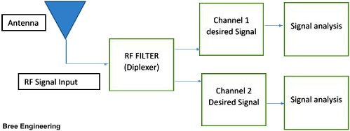
Band Dividers – Rough Broad Band Splitting For band splitting, it is the idea of taking a single signal and splitting it up multiple times. In order for this to happen, the initial signal needs to have a high enough power to allow for the split to occur because some of the power will be lost in the process. It is fairly safe to say that during the signal split approximately 3dB of loss will occur each time a split takes place, depending on the component used the loss could be lower. Band dividers are an important tool that can be used within an overall system to split signals when necessary. Naturally band splitting and power dividers go hand in hand because a signal travels with the power sent through the system. Different power dividers can achieve different levels of splitting and different parameter cut offs. Some of the most popular ones are versions of Directional Couplers, Wilkinson power dividers, and Waveguide Magic Tee Power dividers. Each of these designs has their trade-offs and depending on which design that is chosen you may receive higher insertion loss versus another or the amount of power it can handle. Diplexer
Challenges on the Manufacturing End
The importance of the band dividing, bias T's, and diplexers is that they are crucial to the success of an RF system in need of taking one source and turning it into two sources. In reality all three devices require the same thought process, they all require consideration for sizing and shape due to power handling and bandwidth. Due to the fact that all three components divert the path of a single signal, the core decisions for design and fabrication are critical. About Bree Engineering Bree Engineering Corporation was founded in 1999 and is a manufacturer of custom electronic filters, multiplexers, filter banks and other related types of components in the frequency range of 0.1 MHz to 40 GHz. Contact Bree Engineering for specific applications, Bree Engineering designs include Chebychev, Bessel, Butterworth, Gaussian, Transitional, Elliptic-Function and Pseudo-Elliptic-Function filters. In addition to Lumped Element designs, Bree Engineering also produces Cavity designs (Combline or Interdigital) and Ceramic Resonator designs. Bree Engineering is known for our responsiveness to the needs of our customers, our agility and our consistent on-time delivery. All products are built to your specifications, so if you need a surface mount device or one with connectors, high or low power handling, or optimized for price or any specification parameter you need, we will tell you what is achievable, and explain all of the trade-offs involved so you can make very well-informed decisions.
Posted October 23, 2018 |