|
Electricity - Basic Navy Training Courses NAVPERS 10622 |
|
Here is the "Electricity - Basic Navy Training Courses" (NAVPERS 10622) in its entirety. It should provide one of the Internet's best resources for people seeking a basic electricity course - complete with examples worked out. See copyright. See Table of Contents.
¶ U.S. GOVERNMENT PRINTING OFFICE; 1945 - 618779
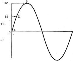
CHAPTER 17 You know the fundamental differences between d.c. and a.c. But a.c. has some special peculiarities all its own. You might say that d.c. plows along like a steady old battlewagon whereas a.c. cuts-up like a frisky P. T. You may be surprised by the way a.c. acts in some circuits. For example, did you know that an a-c coil can be built with only one ohm of resistance and yet pass practically no current at 120 volts? And on the other hand, a condenser, which is made of insulator material, will conduct large alternating currents? A FEW WHYS The basic reason for this behavior lies in the a-c voltage. Look at figure 170. It's only a simple sine wave of a-c voltage. But that sine wave tells you plenty.
To begin with - it's NOT a picture of a.c. Don't get the idea that a.c. humps along like a caterpillar on a wire. It doesn't! Alternating current flows just exactly the way its voltage pushes. And you know that the push reverses its direction every so often. That means the current flows first one way and then the other. The sine wave tells you about this reversal and it also tells you the amount of push at any instant. Look again at figure 170. Imagine that this voltage is impressed on a lamp of 100 ohms resistance. At instant 1, there is zero current because, I = 0/100 = 0. At instant 2, the current is I = 85/100 = 0.85 ampere. And at instant 3 the current is I = 170/100 = 1.7 amperes, or maximum. Notice what was happening between instant 1 and instant 3. The voltage increased from zero to 170 volts. And at the same time, the current increased from zero to 1. 7 amperes. This is the first outstanding characteristic of a.c. A.c. IS CONSTANTLY CHANGING IN VALUE.
Figure 170. - A-C voltage. If you wanted to find the current in an a-c circuit you'd have to apply Ohm's law at thousands of instants. But that would be impossible in a practical circuit, so you use an EFFECTIVE VALUE of a-c voltage and a-c current. The effective voltage is equal to the maximum voltage multiplied by 0.707. Or - Eeff. = 0.707 x Emax.
In the example just used, the lamp would have 170 X 0.707 = 120 volts of effective emf impressed. And the effective current would be 120/100 = 1.2 amperes. You're wondering what the term "effective value" means and where it comes from. It means the amount of a.c. that produces the same heating effect that a given d.c. produces. Here's the problem: You can't take instantaneous readings of a-c current and voltage for every instant on the sine wave. You've got to have some value of a.c. that's a true picture of its ability to do work - that corresponds to d-c values. The maximum value is easiest to determine but it won't do because it's the CORRECT value for only TWO INSTANTS of each cycle. The heating effect of currents is easily measured and this effect is used to establish a comparison between a.c. and d.c. It is found that if the maximum value of the alternating current (Imax) is multiplied by 0.707 the result is the a-c current value corresponding to the d-c current in .heat producing ability. For example, 10 amperes of d.c. produces a certain heat; 10 amperes, EFFECTIVE VALUE, of a.c. produces the same heat. BUT you get this value - 10 amperes of a.c.-by multiplying Imax by 0.707. In this case, 14.14 amperes (Imax) times 0.707 gives you the effective value - 10 amperes. Thus a 10 ampere current in a.c. has a maximum value of 14.14 amperes. But usually this maximum value will cause you no headaches - ALL A-C METERS READ IN EFFECTIVE VALUES. The point you must understand, and remember, is that, although an a-c meter reads a steady current or voltage, NEITHER THE CURRENT NOR THE VOLTAGE IS ACTUALLY STEADY. Both go up and down in value according to their sine waves.
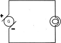
The second outstanding characteristic of a.c. is that it CHANGES DIRECTION AT REGULAR INTERVALS.
Figure 171. - A.c. - d.c. compared. You noticed in the sine wave of figure 170 that half the time the voltage was positive and half the time it was negative. Positive and negative indicate direction. They simply mean that the voltage first pushes in one direction and then in the other. For example, if you had the ordinary D-C circuit shown in figure 171, current would flow from the negative terminal to the positive terminal - ALL THE TIME. But suppose you impress A.C. on this d-c circuit - the current flows from negative to positive HALF THE TIME and from positive to negative HALF THE TIME. The lamp is just as bright on a.c. as d.c. Just as much work is done - just as much power is consumed - provided the a-c effective values equal the d-c values. THREE PURE CIRCUITS There are three things that limit the flow of current in an a-c circuit- RESISTANCE, INDUCTIVE REACTANCE, AND CAPACITIVE REACTANCE. That's two more items than you had in d.c. Remember that resistance ALONE limits current in a d-c circuit. When you have only one factor ALONE - resistance, inductive reactance, or capacitive reactance - you have a PURE circuit. Say you have only resistance in an a-c circuit-then it's a PURE RESISTANCE CIRCUIT. But pure circuits don't happen very often! In fact it's almost impossible to get one. However, by studying the action of pure circuits with anyone of these - resistance, inductive reactance, or capacitive reactance - you get the best picture of how each one of these things affects current. You'll have to remember, though, that most PRACTICAL CIRCUITS are combinations of all three.
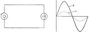
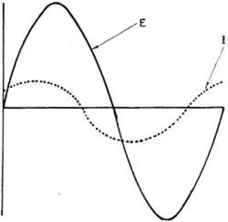
PURE RESISTANCE This one is easy. Just like a d-c circuit, in fact. Figure 172 shows a nearly pure resistance circuit and the sine waves of current and voltage. The voltage impressed on this circuit is shown by the solid line. The current flowing is shown by the dotted line. Just what you'd expect. The current obeys Ohm's law: I = E/R for every instant. Since the resistance is constant, the current rises and falls with the voltage. The sine waves of figure 172 show one very important thing. Voltage and current are exactly IN PHASE - in time. When the voltage is zero, so is the current. When the voltage is maximum, the current is maximum. Pure resistance circuits are IN PHASE circuits.
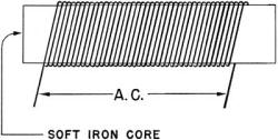
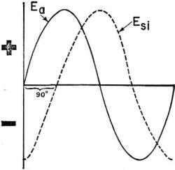
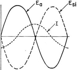
Figure 172. - Pure resistance. PURE INDUCTIVE REACTANCE This one is not so easy, because inductive circuits always contain a voltage of self induction. That means a coil and probably an iron core. To make as pure an inductive circuit as possible, you'd wind a many turn coil on a soft iron core - like figure 173. In an inductive reactance circuit, this is what happens - the expanding and contracting flux, set up by the a.c., produces a voltage of self-induction. In a pure circuit, this self-induced voltage Esi is just as strong as the applied voltage Ea. But the Esi IS NOT IN PHASE WITH THE Ea. Figure 174 shows the first step in understanding a pure inductive circuit.
Notice that the Ea and Esi are 90° put of phase. This out of phaseness was caused by the expanding and contracting flux. Be sure to note that this is the FIRST CONDITION. The complete picture is given in figure 177.
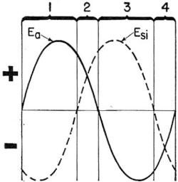
Figure 173. - Pure inductive reactance. Now you have TWO voltages controlling current Ea and Esi. The result is a current out of phase with both. In fact, the current's phase is midway between Ea and Esi. That makes the current 45° out of phase with its applied voltage. Since the current reaches its maximum AFTER the voltage, THE CURRENT LAGS ITS APPLIED VOLTAGE. But this is not the WHOLE picture. The current, by its field, produced the Esi. And if the current moves out of phase - lagging, then the Esi is forced further out of phase, as in figure 175. Notice that the Esi is now opposing the Ea more than half the time. You'll have to look at figure 175 to see what's going on. During the time labeled 1, the two voltages are opposing each other - Esi is negative and Ea is positive. The result is a lowered current because the voltages that should be pushing current are wearing themselves out bucking each other. This same condition is true for the time labeled 3. But, during 2 and 4, the two voltages are aiding each other - the current is pushed in the same direction by both voltages.
Figure 174. - First condition. Which condition has the upper hand - 1 and 3, where the voltages oppose or 2 and 4, where they aid ? Well, which lasts the longest time ? You can see that the opposing condition lasts longer than the aiding. Therefore, the CURRENT IS ACTUALLY REDUCED BY THE OPPOSITION OF THE Esi.
Figure 175. - Second condition.
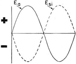
Figure 176. - Third condition. Not only is the current reduced - but it's shoved further out of phase. Current is midway between Ea and Esi, so it must be 67-1/2° lagging its Ea. The third and FINAL condition is shown in figure 176. The current, by moving further out of phase, forces the Esi further out of phase. In turn, the Esi forces the current out of phase. And so on. This is like the question, "Which comes first, the chicken or the egg?" "Which does the forcing out of phase, the Esi or the current?" That's a good question - except -you can't answer it! Each works on the other. Current sets up the field that makes Esi; and Esi always stays 90° away from its current. The Esi helps to push the current, so as Esi gets further out of phase, it carries the current further out of phase. And, as the current gets further out of phase, it forces the Esi still further out of phase because Esi is always 90° from the current.
Figure 177. - Pure inductive reactance circuit. Where is the end to all this pushing further and further out of phase? When the Esi and Ea are 180° out of phase - that's figure 176. Notice that Esi and Ea are opposing each other ALL THE TIME. And, if they're equal - Esi = Ea - the total voltage is zero. Therefore, in a pure inductive reactance circuit, the two voltages - Ea and Esi-and the current would have the phases shown by figure 177.
Inductive reactance does two things to current - REDUCES THE AMOUNT OF CURRENT AND THROWS IT OUT OF PHASE, LAGGING. PRACTICAL INDUCTIVE CIRCUIT If a pure inductive circuit could be built - and it can't be - the current would be lagging 90°. Further, the voltage of self induction would exactly cancel the applied voltage. A pure inductive circuit cannot be built because EVERY CIRCUIT CONTAINS SOME RESISTANCE. Therefore, all practical inductive circuits contain two factors controlling current - RESISTANCE (R) and INDUCTIVE REACTANCE (XL). Both limit current - in this respect they are alike. And both are measured in ohms. But RESISTANCE tends to keep current IN PHASE. And INDUCTIVE REACTANCE tends to force current OUT OF PHASE.
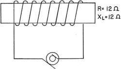
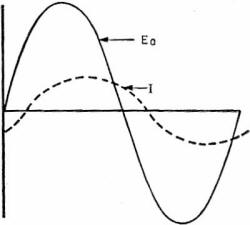
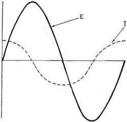
Figure 178. - Practical inductive circuit. A practical inductive circuit - a REAL circuit - contains both inductive reactance and resistance. Look at figure 178-this is a practical circuit. The coil has 12 ohms of resistance (R = 12 Ω) and 12 ohms of inductive reactance (XL = 12 Ω). The inductive reactance (XL) does just as much to limit current as the resistance (R). And the XL exerts just as much force to send the current 90° out of phase as the resistance does to keep it exactly in phase. Result - the current is half way between 90° out of phase, and exactly in phase - it is 45° out of phase, lagging. Figure 179 shows the sine waves of current and voltage for this circuit.
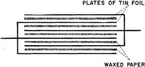
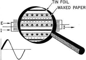
Figure 179. - Current and voltage for figure 178. You can conclude that, in all inductive circuits, the CURRENT IS REDUCED AND LAGS OUT OF PHASE. PURE CAPACITIVE REACTANCE This is another one that is not so easy. Because capacitive circuits contain condensers (capacitors) - and condensers do some strange things. First, you should know how condensers are built. They're made up of alternate layers of conductor and dielectric (insulator) materials. Half of the conductor plates are-connected to one terminal and half to the other terminal. Between every two conductor plates is a layer of dielectric. Many materials will serve as conductors and dielectrics in condensers. But waxed paper is a common dielectric and tin foil is a common conductor. Figure 180 shows a waxed paper and tin foil condenser. Although this condenser is made of only six plates, you'll find many condensers having hundreds of plates.
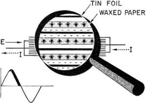
Figure 180. - Simple condenser. Figure 181 shows a condenser with a.c. impressed across its terminal. The "innards" are highly magnified so that you can see what happens inside. During the first quarter of the cycle - that's the first 90° - the condenser is being CHARGED. Voltage is pushing into the condenser from the left (solid arrows). Current is flowing WITH this voltage (dotted arrows). The electrons of the current pile up on the surface of the conductor plates. This gives these plates a negative charge. Repulsion occurs between the conductors negative charge and the electrons in the molecules of the dielectric. The dielectric electrons strain to get away-they move just as far from the conductor's negative charge as they can. This warps the dielectric molecules out of shape. Instead, of nice symmetrical molecules, they're all lopsided - with their electron-congested sides AWAY from the negative conductor plate. Notice, in figure 181, how this builds up a negative charge all along one side of the dielectric plates. Now, compare this to current flow - just about the same, except that the dielectric has NO FREE ELECTRONS to flow. If the dielectric had been a conductor, current would flow in the normal way. So far you've got electrons all piled up along the side of the plates away from the voltage force. The final act comes when the strained dielectric forces electrons out of the conductor plates connected to the right-hand side. Current flows. Electrons came in on the left side-piled up on the plates - repelled the electrons of the dielectric, which in turn repelled the electrons in the plates of the right-hand side. Current flows out of the right-hand side conductor plates. All this is true for the first 90° of the cycle, because voltage is increasing. And as long as voltage is increasing, electrons continue to pile up on the left-hand plates. You can say, that as long as the voltage is INCREASING current flows across a condenser IN THE DIRECTION OF VOLTAGE.
Figure 181. - Condenser action - No. 1. Exactly at the 90° point of the sine wave, everything stands still. Voltage is at its maximum. The condenser is charged. The voltage is no longer increasing, so it can't force any more electrons onto the plates. Current stops. CURRENT IS STOPPED - BUT EVERYTHING IS STRAINED. The left-hand plates have too many electrons. The dielectric's molecules are lopsided, and the right-hand plates have too few electrons. This strained condition is maintained by the maximum voltage at the 90° point in the cycle.
Figure 182. - Condenser action - No. 2. Now, see what happens during the next quarter cycle - the second 90°. Figure 182 shows the same condenser, but during the second quarter of a cycle. When the voltage decreases - from 90° to 180° the strain is relieved - the force maintaining the strain is gradually removed. Every thing returns to normal. And in returning to normal - here's what takes place. The left side loses its excessive electrons. These electrons flow through the external circuit to the right side. Here they fill up the right-hand plates. The dielectric no longer has a charge against it so its molecules spring back to normal symmetrical shapes. The condenser is DISCHARGED. And look what happens during this discharge. In figure 182, you can see that the VOLTAGE is in the same direction as in figure 181 - from LEFT to RIGHT. But CURRENT is from RIGHT TO LEFT (follow the dotted arrows). That's right - current IS flowing AGAINST the applied voltage. And the reason is found in the strained dielectric of the condenser. When that dielectric was being strained by the INCREASING voltage, it was storing energy (much like an emf). When the voltage decreased, the voltage wasn't strong enough to hold the energy in the condenser. Electrons streamed out - backed by the energy of the strained dielectric. These electrons make a CURRENT AGAINST THE VOLTAGE DIRECTION.
Figure 183. - Pure capacitive circuit. These two facts stand out. The current is in the same direction as voltage, as long as voltage is increasing. And the current is in the opposite direction to the voltage, as long as voltage is decreasing. Figure 183 shows you the current and voltage relationships in a pure capacitive circuit. Notice that current LEADS the voltage by 90°. Capacitive reactance (XC) does two things to a current. XC limits current like a resistance and causes current to be out of phase with its voltage LEADING. XC, like XL, is measured in ohms.
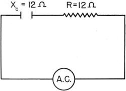
Figure 184. - Practical capacitive circuit. PRACTICAL CAPACITIVE CIRCUIT A practical capacitive circuit - a real circuit - is bound to have some resistance. You can't have any circuit without some resistance. Look at figure 184. The circuit has a condenser with 12 ohms of XC and 12 ohms of R.
Figure 185. - Current and voltage for figure 184. R and XC are equal. They both reduce current flow and the R tends to keep current in phase while the XC tends to force it 90° out of phase-leading. Result-the current is midway between 90° lead-ing and exactly in phase - it is 45° out of phase, leading. The current and voltage relationship is shown in figure 185.
ALL THREE TOGETHER Many circuits are combinations of XL, XC, and R. Ana all of them - XL, XC, and R - have their own individual effect on the current. There is a certain method of combining these three items to give you the IMPEDANCE. Impedance (Z) is the total opposition to the flow of current in an a-c circuit. It corresponds to resistance in a d-c circuit. When you are determining the impedance of an a-c circuit, the first step is to combine the two reactances. They're opposite in action - XL makes current lag and XC makes current lead. Therefore, when they're combined, the action of one cancels the action of the other. If a circuit has 15 ohms of XL and 24 ohms of XC, then the total reactance (X) is 24 - 15 = 9 ohms. And the current will LEAD the voltage because XC is stronger than XL. If a circuit has 30 ohms of XL and 19 ohms of XC, the X is 30 - 19 = 11 ohms. And the current LAGS the voltage because XL is stronger than XC. After you have combined XL, and XC, the total reactance X must be added to the resistance R to get the impedance Z. Here's how you add X and R - Z = SQRT (R2 + X2)
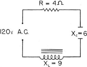
PRACTICE CIRCUIT Take a practice circuit. The one in figure 186 is a good example. In this drawing the resistance and reactance values are given. You can find out HOW MUCH current is flowing, and whether the current is LEADING OR LAGGING.
Figure 186. - Practice circuit. First, how much total reactance? X = XL - XC. X = 9 - 6 = 3 ohms. Second, how much impedance, Z? Z = SQRT (R2 + X2).
Z = SQRT (16 + 9) = SQRT(25) = 5 ohms.
By Ohm's law (but using Z instead of R for - an a-c circuit) you find the current - I = E/Z = 120/5 = 24 amps. And the current is LAGGING because XL is larger than Xc. WHERE THEY ARE You'll find circuits involving XL, XC and R almost everywhere you find a.c. This is only the beginning. Circuits containing a-c induction motors have a high inductive reactance. This makes the current lag too far behind the voltage. So condensers are put in the circuit to increase the XC and offset the XL. Condensers are used in vacuum tube circuits and across switches. Induction coils are used in radio circuits to choke down current. If you keep the three actions straight, you can figure out the effect of each in a circuit. Remember - All three, XL, XC and R limit current. And the total opposition to current flow in a.c. is Z. And Z is made up of XL, XC, and R.
R tends to keep current in phase with voltage. XL tends to make current lag voltage. XC tends to make current lead voltage. Chapter 17 Quiz
|