D-C Motors - Electrical Workers
|
|
Here is the "Electricity - Basic Navy Training Courses" (NAVPERS 10622) in its entirety. It should provide one of the Internet's best resources for people seeking a basic electricity course - complete with examples worked out. See copyright. See Table of Contents. • U.S. Government Printing Office; 1945 - 618779 Studies of motors usually begin with the direct current (DC) type - maybe because most students have already had hands-on experiences with DC motors in models (cars, boats, airplanes) and/or electricity experimenter kits. They are small, cheap, and a simple flashlight battery (the ultimate in safety) makes them run. An alternating current (AC) motor requires either a direct connection to the house current or use of a step-down transformer, which still carries with it a high risk factor. This chapter of the U.S. military's Basic Navy Training Course (NAVPERS 10622) conforms to the tradition, and follows in the next chapter with AC motors and generators. While reading through the text, I ran across the unfamiliar term "kickpipe" and wondered how I could have missed that after so many decades of working with motors - both DC and AC. I didn't feel quite so dumb after looking up the definition; after all, I was in the Air Force, not the Navy ;-) Chapter 15: D-C Motors - Electrical Workers
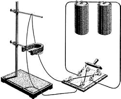
Many men want to know why it is necessary to change the form of power, time after time, in order to get a job done. They want to know why it is necessary to switch from mechanical to electrical and then back to mechanical power. There are a number of reasons why - and all of them good reasons. Suppose the anchor winches, blowers, pumps, and elevators of a ship were operated by steam engines instead of electrical motors. It's not a bad idea, because it would eliminate all the troubles of changing mechanical power to electrical power in turbo-generators and then changing the electrical power back to mechanical power in motors. This electrical system looks like a wasteful proposition. Every change of- power is at an efficiency less than 100 percent, so it involves some loss. If it's wasteful, then, why use it? Because electrical power is the easiest and safest kind of power to use. But to get back to the anchor winch. Running a steam pipe to the anchor winch cuts through many bulkheads and decks. Watertight integrity is upset. But, an electric cable can make the same run and the kickpipes and stuffing tubes through decks and bulkheads preserve watertight integrity. Suppose enemy fire bursts a steam line between the boiler and the steering engines. Power is drained off the boilers and men may be scalded by escaping steam - things are really fouled up. Sure - an electric cable in the same position would be broken too. But what happens? Probably an open circuit results which does not drain power and does not injure anyone. The worst that could happen would be a short circuit, in which case fuses or circuit breakers would quickly open the circuit rendering it harmless. There are many reasons for using electrical motors - they're safe, handy, easily controlled, and easily supplied with power. How a Motor Is BuiltThis is easy-a motor is built just like a generator. The overall name for motors or generators is dynamo. If the shaft of a dynamo is connected to a prime mover and turned - it's a generator - it pumps electrical power out on its lines. If the shaft of a dynamo is connected to a mechanical load - it's a motor - it takes electrical power in on its lines. How It Works
Figure 137. - Conductor in a magnetic field.
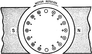
Figure 138. - Motor action.
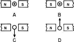
Figure 139. - Applications of the motor hand rule.
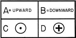
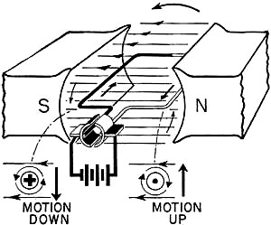
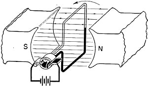
Figure 140. - Answers. In the study of Lenz's law you learned that a current carrying conductor in a magnetic field exerts a force against the field. The force tends to push the conductor out of the field. This is the principle of operation of the motor. The magnetic field is furnished by the pole pieces and frame. As in the generator, the field is stationary and steady. current is sent into the armature windings and sets up a magnetic field around the armature. The two fields - armature and frame - react against each other. The result is a force against the armature windings which tends to push them out of the field. Since these windings are fastened to the armature core and shaft, they tend to move out of the field also. Understanding Motor ActionIf one strand of wire is suspended between the . poles of a horseshoe magnet, as in figure 137, nothing happens. But close the switch, connecting the batteries to the wire, and the wire jumps backwards, into the magnet. Reverse the switch so that current direction in the wire is reversed and the wire jumps outwards away from the magnet. This is proof that there is a force exerted on a current-carrying conductor. The conductor tends to be pushed-out of the field. It is also proof that the direction of push reverses when the current is reversed. As you probably suspect-the direction of push also reverses when the pole pieces change polarity. Figure 138 summarizes motor action. notice, in the A drawings, that the flux above the conductor blends with the flux of the field. The flux below the conductor cancels the field flux. This results. in a strong but distorted field above and a weak field below. The conductor moves downward into the weakest area. In B, the current is reversed - the field below is strong and distorted, and the field above is weak. The conductor moves upward. Evidently, motor action is the result of two magnetic fields reacting on each other. It's a lot like two south or two north poles repelling each other if one of the poles is free to move, a simple motor action is produced. After all, a compass needle reacting in a magnetic field is like a tiny motor. The Motor Hand RuleJust like generators, motors have three "directions" - conductor current direction, field, flux direction, and direction of motion. And again, they are linked together by a hand rule. The thumb stands for the motion of the conductor. The first finger for flux direction and the middle finger for the current direction in the conductor. But here's a change - for motors you use the right hand. Figure 139 will give you some practice in the motor hand rule. In A and B you must determine the direction that the conductor will move. In C and D, determine the direction of current necessary to, produce the motion indicated. Remember you use the fingers of your right hand for motors exactly the same as you used the fingers of the left hand for generators. note - The Warning given on page 140 applies here also. Figure 140 gives you the correct answers for figure 139. Try the motor hand rule on all the diagrams before you check any of your answers. Loop in a FieldThe simplest motor would be a wire in a magnetic field with a mechanical load attached. Every time the circuit was closed, the wire would move, dragging its load with it. When the circuit was reversed, the wire would reverse and push its load back again. This kind of a motor is impractical. In the first place, it's too weak to do much work. And in the second place, straight line, back and forth motion is inefficient and slow. To increase the strength, add more conductors so that the forces add. To eliminate the straight line motion, make the set of inductors rotate. Here's how it's done. A single-turn coil is mounted in a magnetic field as in figure 141. note that the current direction is traced by arrows. The left-hand side of the coil is carrying current IN. And the motor hand rule tells you that this side moves downward. The right-hand side of the coil carries current OUT. And the motor hand rule indicates motion upward. The small drawings, just below each coil side, shows what happens to the flux at each side. Now, if the right side moves up, the left side moves down and the coil is pivoted along its center line - counterclockwise rotation is produced.
Figure 141. - One loop motor action - 1.
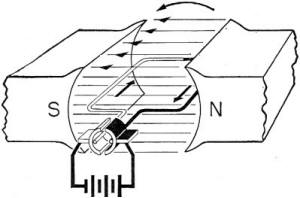
Figure 142. - One loop motor action - 2.
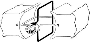
Figure- 143. - One loop motor action - 3.
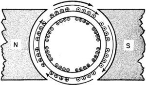
Figure 144. - Two loop motor action. <no photo> Figure 145. - Gramme ring motor action. Figure 146. - Cross section of the Gramme ring. Figure 147. - St. Louis motor.
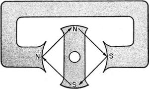
Figure 148. - Torque vectors in the St. Louis motor.
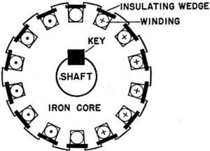
Figure 149. - Cross section of drum winding.
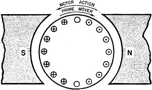
Figure 150. - Motor action in a generator.
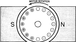
Figure 151. - Generator run as a motor.
Figure 152. - Direction of counter-EMF. The forces against these conductors are straight line forces but because the coil is pivoted, they can't move in a straight line. They are obliged to move in a curve - a part of a circle. When a force produces a circular or twisting motion, the result is called a torque. The torque on this loop continues until it is in the position shown in figure 142. In figure 142, the coil is in the neutral plane - no torque is produced. The segments on the commutator are breaking contact with their brushes. current is about to reverse in the coil by switching brush connections. Even if the brushes were not breaking contact, the torque would be zero-because the upward and downward forces cannot produce rotation from this position. The forces are aligned with the pivoting shaft. No twist - no torque. Will the coil stop on the neutral plane? Only if it is turning very slowly. Usually the momentum is great enough to carry the coil through the neutral plane. Just past the neutral plane the segments switch brushes. This reverses the coil current. Examine figure 143 - the motor hand rule will tell you that the white side of the coil is now forced downward and the black side upward. This keeps the coil rotating in a counterclockwise direction. The total effect of all the forces operating on the coil has been to produce a torque in a counterclockwise direction. One coil turning in a field is a motor all right - but the load it is capable of driving is extremely small. Furthermore, every time the coil passes through the neutral plane, the torque is zero. This zero point introduces a jerk to the rotation. All you have to do to make the motor stronger and to eliminate the zero torque points, is simply add another coil at right angles to the first. Look at figure 144. With two coils arranged like this, only the coil in the best position to produce torque is connected to the brushes. The power is doubled and the points of zero torque are eliminated. The next step is the use of the Gramme ring. armature as a motor. Figure 145 shows both the current direction and the force exerted by each winding. notice that each conductor exerts a force which tends to turn the armature clockwise. As a generator, only the outside conductors of the Gramme ring cut flux and produced voltage. Likewise, as a motor, only the outside wires are acted on by the field flux. In fact, there isn't any flux to act on the inside conductors - it all enters the ring and travels through the iron when going from north pole piece to south pole piece. Figure 146 shows a cross section of a Gramme ring. notice the flux path and the force vectors. Use your motor hand rule on a few conductors on each side of the armature. Prove to yourself that the armature rotates clockwise. St. Louis Type MotorThe St. Louis type motor of figure 147 is not a commercial job. Yet it clearly illustrates motor action. note the two circuits-one through the field poles, the other through the armature. Both circuits do the same thing-each sets up an electromagnetic field. The two fields set up four forces between the armature poles and the field poles. The north pole of the armature is attracted to the south pole of the field and is repelled by the north pole of the field. The south pole of the armature is attracted to the north pole of the field and repelled by the south pole of the field. Two attractions and two repulsions-all four pushing in one rotational direction. Figure 148 shows the four forces as vectors. notice that all vectors are in a clockwise direction - all vectors produce clockwise rotation. You would expect the armature to stop when the armature poles and the field poles are opposite each other (second position of figure 147). It would, except for two reasons. First, the brush connections change segments thus reversing the polarity of the armature. Repulsion and attraction exchange positions. Second, the momentum of the armature carries it past the dead-center position, opposite the poles. If the motor stops at dead-center, it won't be self-starting again because the forces of attraction and repulsion are on a straight line through the shaft. You would have to give it a whirl by hand, so that the armature and field poles are at an angle. Torque is produced only when the forces of the two fields are at an angle to the armature shaft. Drum WindingsThe drum winding for a motor is just like the drum winding for a generator. It is exactly like the armature in figure 133. Another way to picture this armature is by cross section as in figure 149. This figure shows many interesting details of design. notice that every conductor is on the outside of the drum. This means that every conductor is in the flux field and that every conductor exerts a torque. The conductors are set in armature slots and locked in place by insulating wedges. Why? Because the force of electromagnetism on these conductors is tremendous, especially in large motors. If they weren't locked in, they'd be torn off the armature by this force. The motor action of a conductor in a field is a straight line force - the conductor tends to move directly out of the field. By locking it on the armature core, the conductor is forced to drag the armature around with it when motor action takes place. Also, examine the locking "methods between the shaft and core. The shaft is locked by a key to the iron core. Thus, windings, core, and shaft are one mechanical unit turning together. In general, motors are designed and constructed to do just one job-convert the electrical energy of their fields into the mechanical energy of their shafts. There are many modifications of design and several different methods of connection but they all work on the principle that a current carrying conductor is forced out of a magnetic field. The more complex designs and connections which are set up for specific jobs are explained in the books for specific ratings. Motor Action in a GeneratorWhat's the difference between a windmill and a blower-fan? Both are constructed of a number of blades which handle wind. In construction there's no difference. But, in purpose or use, there's plenty of difference. A windmill is turned by moving air and its mechanical power output is used to pump water. A blower fan is turned by a motor or an engine and its power output is used to move air . Construction is the same -but what they do depends on how they're used. What's the difference between a motor and a generator? In construction - there's no difference. In use - there's plenty of difference. Now, the point is - why doesn't the generator act like a motor and why doesn't the motor act like a generator? They do! Remember, or if you've forgotten - review it - the description of a welding generator in Chapter 13. When a load is thrown on this generator, the prime mover whines and shows, that it's working against a load. This load is the generator trying to run as a motor. And the higher the current through the generator (greater load), the harder it tries to run as a motor. Look at figure 150. This is a cross section of a generator. Using the generator hand rule, you see that the current in the windings is induced by clockwise rotation. If there's current in the windings - and there certainly is-those windings are -going to set up fields just like the windings of a motor. Using the motor hand rule, you see that the generator is trying to run as a motor in a counterclockwise direction. The total picture is this - the prime mover is rotating the generator in a clockwise direction, and the fields set up by the induced currents in the armature windings attempt to drive the generator as a motor in a counterclockwise direction. This tendency to oppose the prime mover is called motor action in a generator. The higher the current in the armature windings, the stronger the motor action. Counter-EMF in a MotorNow, how about motors? Do they generate a voltage? Indeed they do, and it's a good thing they do! Motors would burn up if they didn't induce a voltage in the armature windings. Look at figure 151. This is the generator of figure 150 now being used as a motor. You notice that, although the current of the armature is the same in both figures, the rotation is opposite. That should be expected - 150 is a generator and 151 is a motor. As you know, the fields set up around the conductors on the armature react with the fields set up by the pole pieces. Torque is produced and the motor rotates counterclockwise. Check it with the motor hand rule. As the armature rotates, its conductors cut through the field flux. A voltage is induced in these conductors. Using the generator hand rule for this generated voltage you'll find that it is opposite to the voltage applied at the brushes. Figure 152 shows the direction of the applied volt-age and the direction of the generated voltage. The generator and motor hand rules tell you that the generated and applied voltages in a motor are always opposite. The generated voltage in a motor is called counter-EMF. This means that there are two voltages operating on every conductor on the armature of a motor. Moreover, these two voltages are opposing each other. current, then, is the result of a combination of the two voltages. It is possible to prove that the counter-EMF is always less than the applied EMF. Say that the armature of figure 152 has a resistance of 0.5 ohm. The applied voltage is 110 volts. This is what happens when the switch is closed. WHAM! - 110 volts pushing current through 0.5 ohms resistance. I = E/R = 110/0.5 = 220 amps. This 220 amperes of current flowing through the small windings of an armature-it would really cook! But, wait - is there a current of 220 amperes in this armature? Yes, there is - but only at the instant of starting. As soon as the armature starts to turn, it produces a counter-EMF, opposite to the 110 volts of applied EMF. When it is turning at one-quarter speed, the counter-EMF is 25 volts. The net voltage across the armature is 110 volts minus 25 volts or 85 volts - the voltages are subtracted because they are opposite. The 25 volts of counter-EMF cancels 25 volts of the applied EMF, leaving 85 volts to push current. Now the current through the armature is - I = E/R = 85/0.5 = 170 amps. Still very much too high, but getting smaller! At one-half speed, the counter-EMF is 50 volts, the net voltage is 110 - 50 = 60 v., and the current is - I = E/R = 60/0.5 = 120 amps. current value is dropping as counter-EMF In-creases! At three-quarters speed, the counter-EMF is 75 volts, and the current is - I = E/R = 35/0.5 = 70 amps. This is getting close to a safe value! At full speed the counter-EMF is 100 volts and current is - I = E/R = 10/0.5 = 20 amps. current is at a normal, safe value! Why did the counter-EMF become stronger as the speed increased? Because more lines were cut per second as speed increased. This connection between speed and counter-EMF is a perfect current control. When the motor is going slow it needs a high current in its armature. The high current makes a strong field and the motor's torque drives it to a higher speed. As the speed increases the counter-EMF also increases, and the net voltage becomes less. This causes the current to decrease - and that's just right. Because, as speed in-creases, the motor doesn't need as strong a torque to increase or maintain its speed. Finally, when the motor reaches full speed, the torque and consequently armature field) that is needed, is relatively small. The counter-EMF at full speed is high and allows just enough current to pass through the armature to maintain speed. From this example, two facts stand out - the counter-EMF is directly proportional to speed. The armature current decreases as the counter-EMF increases. Loading a MotorImagine that the motor just studied is rotating at a full speed of 4,000,and is driving a water pump. The pump is delivering 100 gallons of water per second. Now you double the load by connecting to a pump delivering 200 gallons of water per second. Of course you first make sure that the motor is LARGE enough to handle the additional load. With the doubled load, the motor needs twice as much power and it gets it by counter-EMF adjustment. Here's how it works - with the doubled load, the motor slows down to 3,600 rpm, and at this speed, the counter-EMF is only 90 volts. The net voltage increases from 10 volts to 110 - 90 = 20 volts. At 20 volts net voltage, the current is - I = E/R = 20/0.5 = 40 amps. Or, exactly twice as much current to handle twice as much load. Here is the formula for determining the armature current - Ia = (Ea - Eg)/Ra in which Ia = the armature current, in amperes; Ea = the applied voltage, in volts; Eg = counter-EMF, in volts; Ra = resistance of the armature, in ohms. notice that his formula is a form of Ohm's law. The E in Ohm's law has been changed to Ea - Eg because this is the actual voltage forcing current. Counter-EMF is like a valve in a water pipe. If you want a lot of water, you open the valve. If you want a little water, you partially close the valve. If a motor needs a lot of current to handle its load, it slows down thereby decreasing the counter-EMF and allowing a high current into the armature. If a motor needs only a little current, it speeds up so that the counter-EMF is just the right value to let enough current through the armature to handle the load. You might say that this is like the transmission in an automobile. Low gear gives the most torque but the lowest speed. High gear gives the highest speed but the least torque. In a motor high speed means high counter-EMF and low current and torque (light loads). Low speed means low counter-EMF and high current and torque (heavy loads). Starting Motors
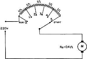
Figure 153 - Motor with starting rheostat. The motor of figure 153 has 550 amperes through its armature at the instant of starting. If it started very quickly and built up speed, the counter-EMF would choke off this high current before any damage is done to the windings. But large motors are too heavy to start quickly-it takes time to build up speed and counter-EMF. You can't get a motor- - . cycle pickup out of a five-ton dump truck! Therefore, large motors get altogether too much current at the start. To cut down this starting current, a rheostat is connected in series with the armature. When the motor is started, the resistance is cut in-limiting the current to a safe value. As the speed picks up, the resistance is gradually cut out of the circuit because the counter-EMF is taking its place in reducing current. Figure 153 shows a 7% HP motor with a starting rheostat. All the electrical values, are labeled. If this motor were , started without the resistance, the armature current would be - Ia = (Ea - Eg)/Ra = (220 - 0)/0.4 = 550 amps. and normal full load current is only about 40 amperes. You KNOW the damage that would result from this excessive current. The rheostat in series with the armature has a resistance of 1 ohm per unit. When the motor is started all five units are cut in, and the current is - I = E/R = 220/5.4 = 40.7 amps. As the speed of the motor increases the rheostat arm is moved progressively from point 5 to point 0, thus cutting down the added resistance from 5 ohms to zero as the counter-EMF builds up. To put it briefly - the rheostat simply takes the place of the counter-EMF when the counter-EMF is too low to do its own job of limiting the armature current. When rheostats are combined with certain other pieces of electrical apparatus, they are called starters. Starters are used for all d-c motors over 5 HP and for almost all motors between 1 HP and 5 HP. Usually no starter is used on small motors - under 1 HP. The most important function of starters is to limit the armature current by a rheostat. Other functions of a starter are explained wherever needed in the books for specific ratings. Reversing
Figure 154 - Reversing motors. Compare the four motors shown in figure 154. A and B have their armature currents in opposite direction. Using the motor hand rule, you'll find that their rotations are opposite. The currents in the field windings of C and D are opposite, therefore their field polarities are opposite. Using the motor hand rule, you'll find that their rotations are also opposite. Finally, compare A and D. The fields of these two motors are opposite. Also, the currents in their armatures are opposite. But the motor hand rule shows that A and D have the same rotational direction. Thus, you can reverse the direction of rotation of a motor by either reversing the armature current or reversing the field current. But not by reversing both armature and field. Navy methods call for always reversing the armature current in order to reverse rotation. Here's a tip-the easiest way to reverse the current direction in any winding is simply by reversing the lead connections.
Posted June 12, 2020 Chapter 15 Quiz |