RF Schematic & Block Diagram Symbol Stencils for Visio™ - v2These stencils have been superseded by RF & Electronics Symbols v2020™ for Visio™ |
|
Of course if you have the non-colored version, you can always just add your own color. However, some of the newer symbols have been changed a bit, and entirely new symbols have been added. Most of the stencils are for RF, microwave, and wireless drawings, but a few are included for standard electronic schematics since often the two types are combined. Visio has a lot of built-in symbols for electronics. The block diagram at the right is an example of what can be done with the new symbols. Connection points are provided on everything for exploiting Visio's built-in Connector lines that automatically follow a symbol if it is moved on the page (it's easy enough to add them yourself to the v1 version). Combined with the selection of objects supplied with the Visio software, everything you need to create presentation quality drawings is available.
Includes 2008
ARRL Handbook Symbols!
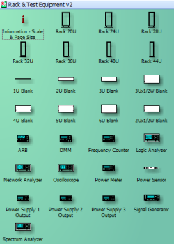
The EIA standard equipment rack and test equipment stencils now have text that scales with the stencil as it is varied. Doing so required modifying the ShapeSheets with an equation in the text size field. It was a lot of work, but definitely worth the effort. The v1 stencils required you to manually re-size the text if you resized the racks or TE. As with the other v2 components, color has been added to everything. As with the v1 rack & TE stencils, they are built full-size at a 1:1 scale, so everything is directly measurable without scaling. Your page size is set to the real-life size and everything will fit exactly as it would if you printed it out full-size. Of course, you can tell Visio to print it to fit on a standard size piece of paper.
Example of the Racks and Test Equipment To right and left are screen captures of the actual Stencil windows that show all the available components. RF Stencils for Visio v1 had two versions of most components - both horizontally and vertically oriented - in order to accommodate the grouped text fields for parameter specification.
Equipment Rack / Test Equipment Visio Stencils
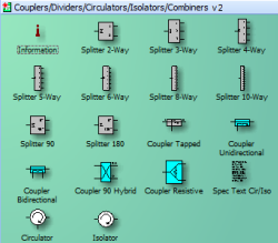
Coupler / Divider / Circulator / Isolator Visio Stencils
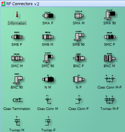
RF Connector Visio Stencils
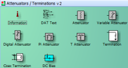
Attenuator / Termination Visio Stencils
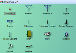
Antenna Visio Stencils
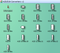
A2D / D2A Converter Visio Stencils
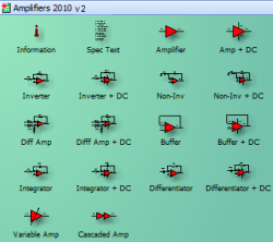
Amplifier Visio Stencils
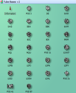
Tube Base Visio Stencils
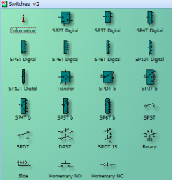
Switch Visio Stencils
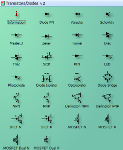
Transistor / Diode Visio Stencils
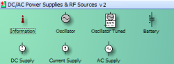
AC / DC Power Supply Visio Stencils
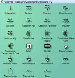
Resistor / Capacitor / Inductor Visio Stencils
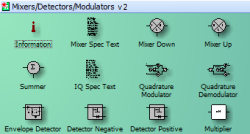
Mixer / Modulator / Detector Visio Stencils
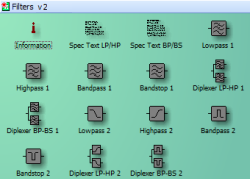
Filter Visio Stencils
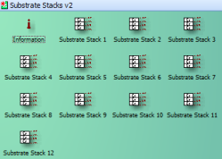
Substrate Stack Visio Stencils Rather than clutter the stencil selection with essentially redundant components, a single version is provided, and the specification text, where applicable, is provided as a separate component. You can of course add your own text objects to the drawing, just as you can add any other type of Visio built-in objects.
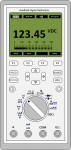
Says Bob: "I needed a Handheld DMM stencil, so I created one loosely modeled on a Fluke 289. Attached is a *.vsd file containing two versions -- the "Original" is grouped, but editable; the Metafile version is scalable (created by copying the original and doing a "Paste Special" in metafile format). " How to open these stencils in Visio 2010?** Make certain that the Color Themes are set to "None" **
In Visio 2013, you will probably need to change the File Block Settings that have been added in 2013 for security purposes. Please see the Microsoft support page for detailed instructions on File Block Settings (it's easy to do). |